
Interface an Arduino with PIR module
Motion detection plays a crucial role in many projects, and with the advent of the PIR (Passive Infrared) Sensor, detecting human or animal movements has become easier than ever. In this project, we will explore how to interface a PIR Sensor with an Arduino microcontroller. The goal is to make an LED blink and a buzzer beep whenever movement is detected. Below is a list of components required to build this project.
TRAINING
2/1/20254 min read
Introduction:
Motion detection plays a crucial role in many projects, and with the advent of the PIR (Passive Infrared) Sensor, detecting human or animal movements has become easier than ever. In this project, we will explore how to interface a PIR Sensor with an Arduino microcontroller. The goal is to make an LED blink and a buzzer beep whenever movement is detected. Below is a list of components required to build this project.
Materials Required:
PIR Sensor Module
Arduino UNO (any version)
LED
Buzzer
Breadboard
Connecting Wires
330-ohm Resistor
PIR Sensor:
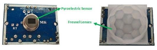
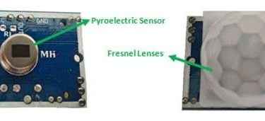
A PIR (Passive Infrared) sensor is a low-cost sensor that detects the presence of humans or animals by sensing infrared radiation. The sensor is equipped with two key components: a pyroelectric crystal, which detects the heat signatures of living beings, and a Fresnel lens, which expands the sensor's range. Additionally, the PIR sensor modules come with settings to adjust the sensor’s functionality for different needs.
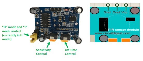
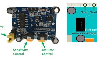
The two potentiometers (orange) on the PIR sensor module are used to adjust its sensitivity and the trigger duration. The module's Dout pin is positioned between the Vcc and Gnd pins. While the sensor typically operates at 3.3V, it can also be powered with 5V. In the top-left corner of the module, there is a trigger pin that allows you to switch between two modes: “H” mode and “I” mode.
In “H” mode, the output pin (Dout) goes high (3.3V) when a person is detected within the sensor's range and stays high for a set time, which is determined by the potentiometer. This output remains high even if the person leaves the area before the set time elapses. For our project, we’ll use the module in “H” mode.
In “I” mode, the output pin (Dout) goes high (3.3V) when a person is detected and remains high as long as the person stays within the sensor's range. Once the person leaves the detection zone, the output pin will go low after the set time expires, which is also adjustable using the potentiometer.
Note: The placement of the potentiometers or pins may vary depending on the PIR sensor model. Always refer to the silk screen to confirm the pinouts.
Circuit Diagram and Explanation:
The circuit diagram for the Arduino motion detector project, which interfaces the Arduino with the PIR module to blink an LED and activate a buzzer, is shown below.
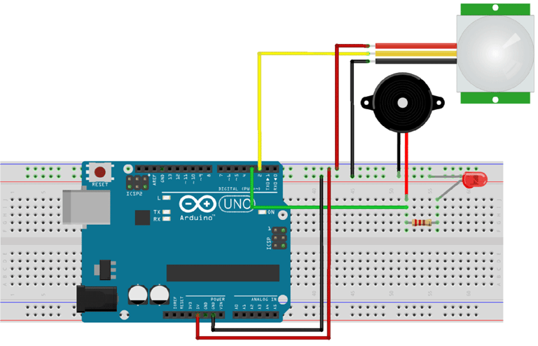
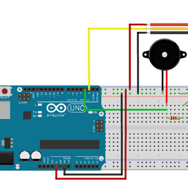
The PIR sensor is powered through the 5V rail of the Arduino. The output pin of the PIR sensor is connected to the Arduino's digital pin 2, which will serve as an INPUT pin for the Arduino. Digital pin 3 of the Arduino is connected to both the LED and the buzzer, acting as an OUTPUT pin. We will write a program for the Arduino that triggers the output on pin 3 whenever input is detected on pin 2. The full program is explained in the section below.
Programming the Arduino:
The Arduino program is simple and straightforward. To interface the PIR sensor with the Arduino, we first need to define pin 2 as the input and pin 3 as the output.
Next, the program will generate a discontinuous trigger whenever pin 2 goes high (detects motion). Each line of the code is explained in the following section.
int ledPin=3; // initialising the pin 12 as the led pin
int sensorPin=2; // initialising pin 8 as the sensor output pin
int buzz=2;
boolean val =0;
void setup(){
pinMode(ledPin, OUTPUT); // set arduino pin to output mode
pinMode(buzz, OUTPUT); // set arduino pin to output mode
pinMode(sensorPin, INPUT); // set arduino pin to input mode Serial.begin (9600);
}
void loop () {
val =digitalRead(sensorPin);//read the sensor pin with the digitalRead() function and store the value to the val variable. Serial.println (val);
if (val==HIGH) // when the sensor detects a signal above the threshold value, LED flashes {
digitalWrite(ledPin, HIGH); //LED turns ON }
else { digitalWrite(ledPin, LOW);//LED turns OFF }
}
Working:
The circuit and program for this Arduino motion detector project have been explained above. Now, you can assemble the circuit on a breadboard by following the provided schematic and upload the program, which is included at the end of this document. Once you have completed the connections, your setup should resemble the one shown below.
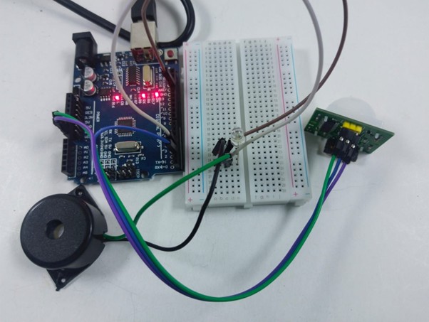
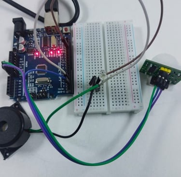
Fig: LED and buzzer is OFF when no motion is detected
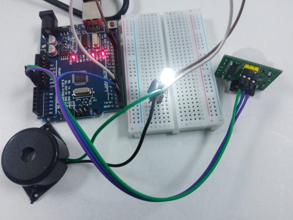
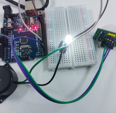
Fig: LED is turned ON when motion is detected by the PIR sensor
Power on the Arduino and allow the PIR sensor to calibrate for about 50-60 seconds. Don’t worry if you see unexpected behavior during this time. After the calibration period, try moving in front of the PIR sensor, and the LED/buzzer should activate.
The beeping or flashing will stop after a while. You can adjust the potentiometer to experiment with the sensitivity or the duration of the trigger (low time) to fine-tune the module's response.