
Interface the Hall effect sensor with Arduino.
A Hall Effect sensor, also known as a Hall sensor, is a non-contact magnetic sensor that is sensitive to a magnetic field, producing a voltage to represent the applied magnetic field. They are very widely used in industries in such applications as current sensing, position detection, contactless switching, and many others. They work like a reed switch: the output voltage varies with time according to the surrounding magnetic flux. Hall Effect sensors are widely used in BLDC applications because they are robust, accurate, and have a very low failure rate.
TRAINING
1/30/20257 min read
A Hall Effect sensor, also known as a Hall sensor, is a non-contact magnetic sensor that is sensitive to a magnetic field, producing a voltage to represent the applied magnetic field. They are very widely used in industries in such applications as current sensing, position detection, contactless switching, and many others. They work like a reed switch: the output voltage varies with time according to the surrounding magnetic flux. Hall Effect sensors are widely used in BLDC applications because they are robust, accurate, and have a very low failure rate.
In this tutorial, we will learn how to connect a Hall Effect sensor to an Arduino. The module can be configured to work with either analog or digital output modes. We will measure its output and use that to control the onboard LED of the Arduino.
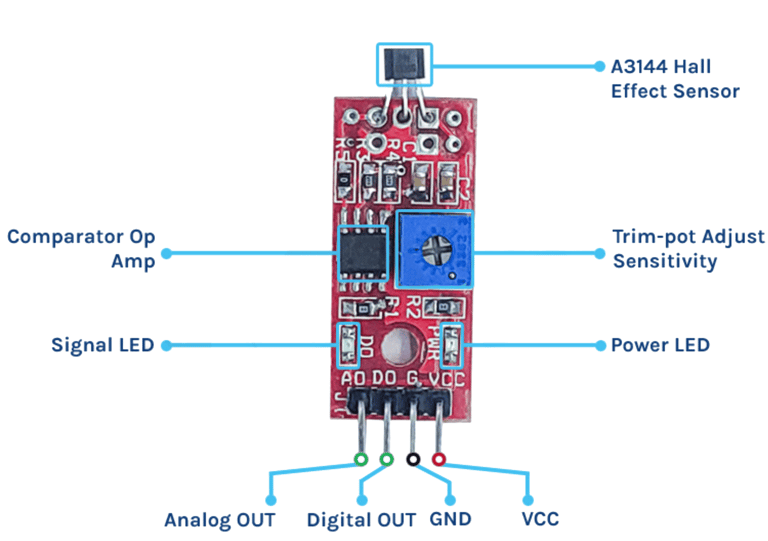
Hall Effect Sensor Pinout
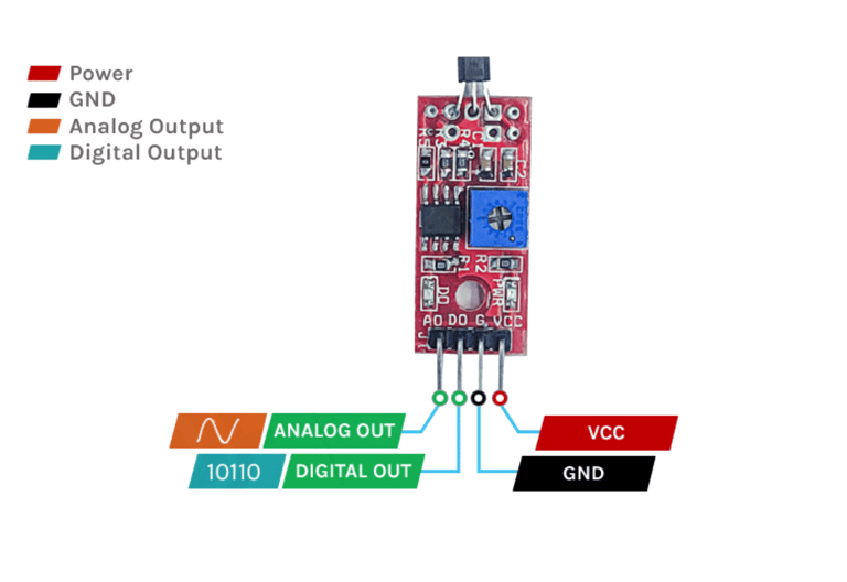
The Hall Effect sensor module has four pins:
VCC: The power supply pin, connected to the 5V pin on the Arduino.
GND: The ground pin, linked to the Arduino’s ground.
DOUT (DO): Digital output pin—LOW when no magnetic field is present, HIGH when a magnetic field is detected.
AOUT (AO): Analog output pin—provides an analog reading corresponding to the magnetic flux.
Working Principle of Hall Effect Sensor
Hall Effect sensors operate based on the Hall Effect principle. The Hall elements consist of a thin rectangular piece of p-type semiconductor material like Gallium Arsenide, Indium Arsenide, or Silicon. The current in the Hall element flows continuously. The presence of a magnetic field in the vicinity of the sensor will cause magnetic flux to apply a force to the semiconductor that pushes the charge carriers to the two sides of the semiconductor. This displacement produces a potential difference due to the collection of charge carriers. The electrons move under the external magnetic field; this phenomenon is more important in a flat, rectangular material. The power to create a measurable voltage using a magnetic field is called the Hall Effect.
In the absence of a magnetic field, the analog output stays approximately at 50% VCC. Introducing a magnet changes the output voltage in that it increases when a south pole is present or decreases when a north pole is introduced. It depends on how strong the magnetic field is. A digital output is derived by an LM393 comparator circuit with a status LED that goes out if a magnetic field is sensed on the module.
Types of Hall Effect Sensor
The main classification of the Hall effect sensor is based on the output signal type – analog output Hall effect sensor and Digital output Hall effect sensor.
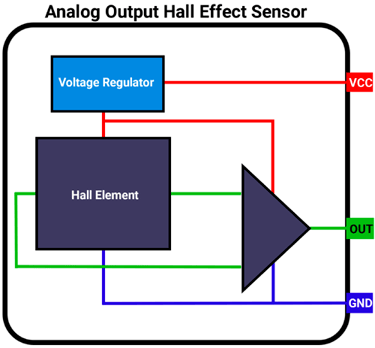
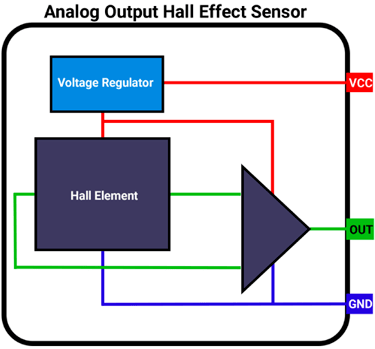
Analog Output Hall Effect Sensor
An analog Hall Effect sensor consists of three key components:
Voltage Regulator – Ensures stable power supply to the sensor.
Hall Element – Detects the presence and strength of a magnetic field.
Differential Amplifier – Processes the output signal.
This type of sensor provides an analog output that is directly proportional to the strength of the magnetic field.
When no magnetic field is present, the Hall voltage is zero. However, if the voltage at each output terminal of the Hall element is measured relative to the ground, a non-zero voltage is observed at both terminals. This voltage is called common-mode voltage and is identical at both outputs.
To eliminate this common-mode voltage and extract a meaningful signal, a differential amplifier is used. A common example of such a sensor is the 49E Hall Effect sensor.
Digital Output Hall Effect Sensor
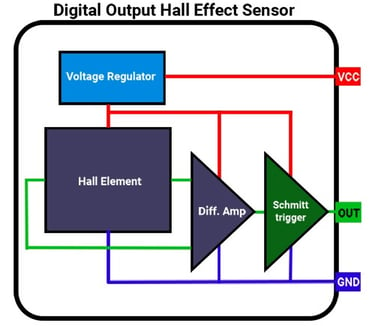
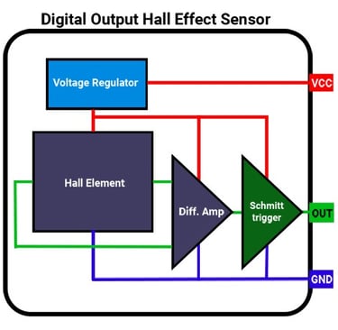
An analog Hall Effect sensor can be modified to provide digital output by integrating a Schmitt trigger at the output of the differential amplifier.
The Schmitt trigger functions as a comparator, measuring the amplifier's output against a predefined threshold:
When the amplifier output exceeds this threshold, the Schmitt trigger turns ON.
When the amplifier output drops below the threshold, the Schmitt trigger turns OFF.
As a result, the sensor operates in a binary mode, providing only two output states: HIGH or LOW. A common example of a digital Hall Effect sensor is the A3144.
Types of Digital Hall Effect Sensors
Digital Hall Effect sensors are categorized based on their ability to detect magnetic poles:
Unipolar Sensors – Detect only one magnetic pole (either north or south).
Bipolar Sensors – Detect both north and south poles.
Components of the Hall Effect Sensor Module
This module is equipped with an analog Hall Effect sensor, which detects the presence of a magnetic field. It is commonly utilized for measuring the RPM of rotating components by sensing a magnet that repeatedly moves in and out of range as the assembly rotates. Additionally, Hall Effect sensors can be employed for detecting electrical current flow through conductors in certain applications.
The module comprises:
Hall Effect Sensor – The core component that detects magnetic fields.
High-Precision Comparator Circuit – Converts the sensor's analog signal into a digital output.
Analog Output – Directly obtained from the Hall sensor and connected to a bypass capacitor and a pull-up resistor for stability.
LM393 Dual Comparator Chip – A widely used operational amplifier that digitizes the analog signal from the Hall sensor.
Trim-Potentiometer (Trim-Pot) – Allows sensitivity adjustment for fine-tuning the sensor’s response.
The Hall effect sensor module circuit is straightforward and requires only a few components. In the schematic, the analog output is taken directly from the Hall effect sensor. The digital output, however, is processed through an LM393 comparator. The power LED is connected directly to the VCC, lighting up as soon as the power supply is connected. The status LED stays on when there is no signal and turns off when a signal is present at the digital output pin. A trim-pot is used to adjust the sensitivity, determining the threshold at which the digital output becomes high.
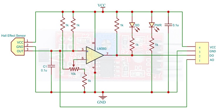
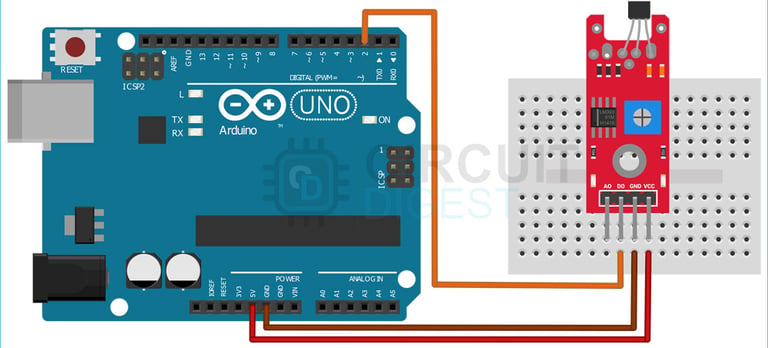
Circuit Diagram for Hall Effect Sensor Module
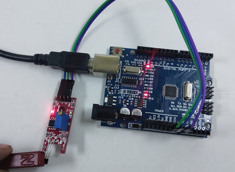
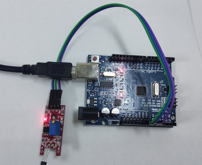
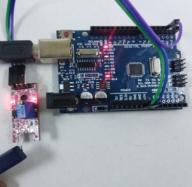
To test the Hall Effect Sensor for digital output, connect the module to the Arduino as shown below. The connections are straightforward. You can use either the digital or analog output from the sensor, but here we will use the digital output. Connect the VCC pin to the Arduino's 5V pin and the GND pin to GND. Then, link the DO pin to the D2 pin on the Arduino. Once the connections are made, we can move on to the code.
Arduino Hall Effect Sensor – Connection Diagram
Digital
The wiring process is straightforward, as the sensor module provides both digital and analog outputs. In this setup, we will use the digital output.
Connections:
VCC → Connect to the 5V pin of the Arduino
GND → Connect to the GND pin of the Arduino
DO (Digital Output) → Connect to D2 pin of the Arduino
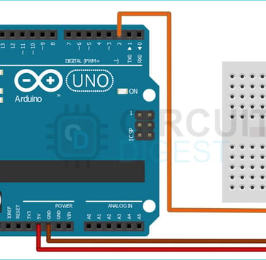
Analog
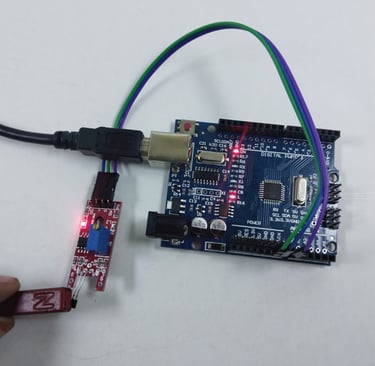
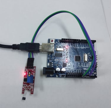
Now let’s connect the module to the Arduino and test it out for digital output. For that, make the connections as shown below.
The wiring process is simple, as the sensor module provides both digital and analog outputs. In this setup, we will use the analog output.
Connections:
VCC → Connect to the 5V pin of the Arduino
GND → Connect to the GND pin of the Arduino
A0 (Analog Output) → Connect to the A0 pin of the Arduino
Arduino Code for Interfacing Hall Effect Sensor with Arduino
The code for interfacing the Hall Effect sensor with an Arduino is straightforward and easy to grasp. The program continuously monitors the D2 pin, which is connected to the DO (Digital Output) pin of the sensor module.
Functionality:
When the sensor detects a magnetic field, the output goes HIGH, and the onboard LED turns ON.
When no magnetic field is present, the sensor output is LOW, and the LED turns OFF.
Note: The status LED on the sensor module operates in an inverted manner—it remains ON when no magnetic field is present and OFF when a magnetic field is detected.
Analog code
int analogPin = A0; // connect sensor A0 to arduino A0
void setup()
{
pinMode(analogPin, INPUT);// set analog pin to input mode
Serial.begin(9600);
}
void loop()
{
int analogVal = analogRead(analogPin);//reads the analog values from sensor amd stores in the analogVal variable
Serial.println(analogVal);//prints the analogVal varaible
delay(100);
}
Digital Code
int digitalPin = 2; // connect GPIO 2 to sensor D0 pin
void setup()
{
pinMode(digitalPin, INPUT);//set digital pin to input mode
Serial.begin(9600);
}
void loop()
{
int digitalVal = digitalRead(digitalPin);//reads the digital values from sensor amd stores in the digitalVal variable
Serial.println(digitalVal);//prints the digitalVal variable
delay(100);
}
Working
Digital


Analog
NOTE:
These outputs are obtained when magnet is placed on the flat surface of the sensor it works exactly opposite when magnet is placed on the other side (curved) of the sensor
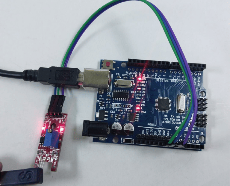
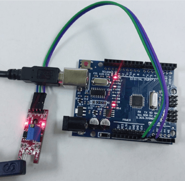


Fig: analog values are decreased for south pole of the magnet and on board led is
ON
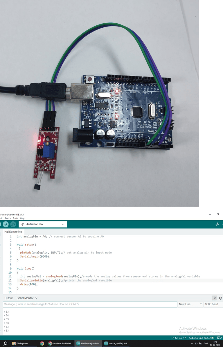
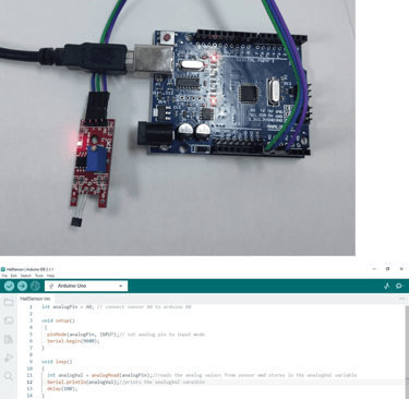
Fig: analog values are neutral in the absence of magnet and on board led is OFF
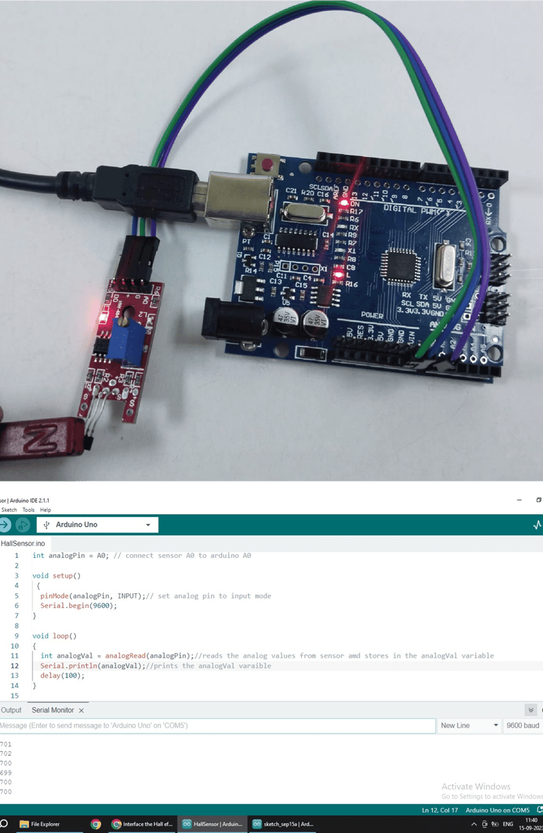
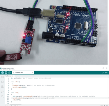
Fig: analog values are increased for north pole of the magnet and on board led is
OFF