
Interface the Rain Sensor with an Arduino
Weather conditions can be highly unpredictable, and rainfall is one of the most unexpected factors. In this article, we will explore how to interface a Rain Sensor with an Arduino. The Rain Sensor, also known as a Rain Detector, is a simple and user-friendly device designed to detect rainfall. It functions like a switch—activating when raindrops fall on the sensor's surface. Additionally, with slight modifications in the code, the sensor can also measure the intensity of rainfall.
TRAINING
1/31/20256 min read
Interface the Rain Sensor with an Arduino
Introduction:
Weather conditions can be highly unpredictable, and rainfall is one of the most unexpected factors. In this article, we will explore how to interface a Rain Sensor with an Arduino.
The Rain Sensor, also known as a Rain Detector, is a simple and user-friendly device designed to detect rainfall. It functions like a switch—activating when raindrops fall on the sensor's surface. Additionally, with slight modifications in the code, the sensor can also measure the intensity of rainfall.
Key Features of the Rain Sensor Module:
It includes a built-in indicator LED for status monitoring.
The module has an onboard potentiometer that allows you to adjust sensitivity for the digital output signal.
Rain Detection Sensor Pinout
Like Soil Moisture Sensor, the Rain detection sensor module also has four pins VCC, GND, A out, and D out that can be used to get the needful information out of the sensor, The pinout of the Rain Detection Sensor is given below:
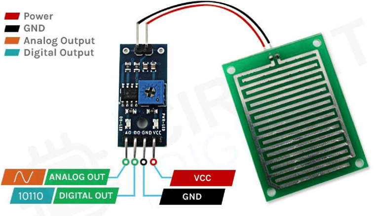
VCC: This is the power supply pin of the Rain Detection Sensor, which can be connected to either 3.3V or 5V. However, keep in mind that the analog output varies depending on the supplied voltage.
GND: The ground pin of the sensor, which should be connected to the GND pin of the Arduino.
DOUT: The Digital Output pin—LOW indicates that rain has been detected, while HIGH signifies no rainfall.
AOUT: The Analog Output pin provides an analog signal that varies between VCC and GND, depending on the amount of water on the sensor surface.
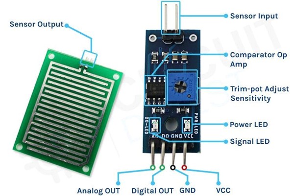
Rain Detection Sensor - Parts
The rain detection sensor module is composed of two main components:
Rain Detection Sensor PCB – This detects the presence of rain.
Signal Processing Module – This processes the data received from the sensor PCB and provides both analog and digital outputs simultaneously.
The module features four pins: two for power (VCC and GND) and two for data output (analog and digital).
Key Features:
Onboard LEDs: The power LED lights up when the module is powered, and another indicator LED turns on when the detected rainfall exceeds the preset threshold set by the potentiometer.
Comparator OP-Amp: Converts the analog signal from the sensor PCB into a digital output.
Adjustable Sensitivity: A built-in potentiometer allows fine-tuning of the sensor’s sensitivity.
Integrated System: The rain detection PCB and the signal processing module work together to form a complete rain detection system.
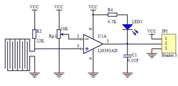
Rain Detection Sensor Module Circuit Diagram
The schematic diagram of the Rain Detection Sensor module is quite simple and requires only a few generic components to build. If you don’t have a prebuilt module but still want to experiment with your project, the provided schematic will be useful.
Circuit Breakdown:
LM393 Op-Amp: The module features an LM393 low-power op-amp with minimal offset voltage, which can operate on either 3.3V or 5V. Keep in mind that the analog output voltage of the sensor will vary based on the supply voltage.
Analog to Digital Conversion: The primary function of the op-amp is to convert the incoming analog signal from the sensor probe into a digital output.
10K Potentiometer: This adjustable resistor is used to set a reference voltage for the op-amp. If the sensor’s input voltage falls below this threshold, the op-amp’s output switches to LOW.
Onboard LEDs:
Power LED: Indicates when the module is powered.
Trigger LED: Lights up when the sensor detects rainfall and the threshold level is reached.
Interfacing the Rain Sensor with Arduino
Now that we have a clear understanding of how the Rain Detection Sensor operates, we can proceed with connecting it to the Arduino UNO. This section will be divided into two parts: one demonstrating the analog output and the other focusing on the digital output. Let's start by exploring the analog circuit configuration.
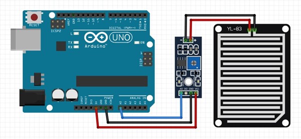
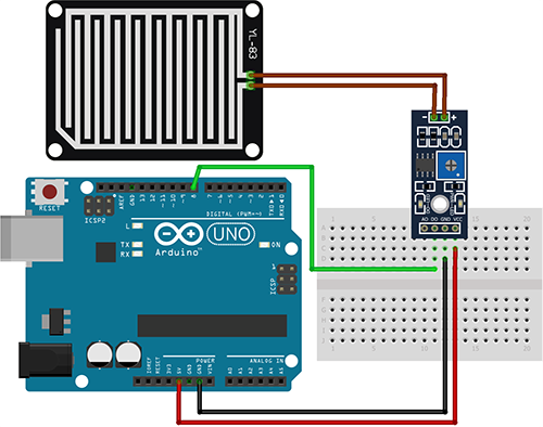
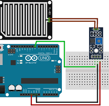
Rain Detection Sensor - Analog Output
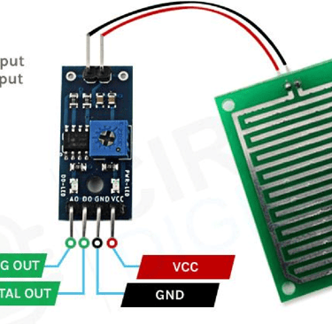
To use the Rain Detection Sensor, we first need to supply power to it. For this, we connect the VCC and GND pins of the sensor to the 5V and GND pins of the Arduino UNO, respectively. The wiring diagram for the analog setup is illustrated below.
As shown in the diagram, the analog output pin (AOUT) of the sensor is connected to the A0 pin of the Arduino. The GND pin is shared between the sensor module and the Arduino, while the VCC is sourced from the 5V pin of the Arduino.
Rain Detection Sensor - Digital Output
For the digital interface, we use the 5V and GND pins of the Arduino to power the sensor module.
Since the digital output functionality is straightforward, we have not included a separate demonstration. However, as shown in the practical example, the onboard trigger LED on the module illuminates when water is detected on the sensor.
With this setup complete, you’re now ready to upload the necessary code to the Arduino UNO and start using the Rain Detection Sensor. You can also see the module in action at the end of this article.
Arduino Code for Processing Data from the Rain Detection Sensor
The Arduino Rain Sensor code is straightforward and easy to follow. In analog mode, we simply read the sensor's analog output to estimate the average rainfall on its surface.
In digital mode, we adjust the onboard potentiometer to set the trigger point. The sensor provides a digital output when the threshold is reached, which can be verified by observing the onboard LED—it lights up when the trigger condition is met.
Digital code:
int rainpin=8;// initialising pin 8 as the sensor output int LED=12;// initialising the pin 12 as the led pin void setup() { pinMode(rainpin,INPUT);// set arduino pin to input mode pinMode(LED,OUTPUT);// set arduino pin to output mode
} void loop() { int val; val=digitalRead(rainpin);//read the sensor pin with the digitalRead() function and store the value to the val variable.
if(val==0) // when the sensor detects a signal above the threshold value, LED flashes { digitalWrite(LED,HIGH);//led on delay(1000); } else { digitalWrite(LED,LOW);//led off delay(1000);
}
}
Analog code:
int rain_sensor = A0; float rain_value; void setup() {
pinMode(rain_sensor, INPUT); Serial.begin(9600);
} void loop()
{
rain_value = analogRead(rain_sensor); Serial.print("Rain sensor value: "); Serial.println(rain_value); if(rain_value > 800) {
Serial.println("No rain detected");
} if(rain_value < 800 && rain_value > 300) {
Serial.println("Medium rain detected");
} if(rain_value < 300) {
Serial.println("Heavy rain detected"); } delay(1000); }
For demonstration in the analog mode, we have connected an LED to the digital pin 6 of the Arduino and we will change the brightness of the LED depending upon the water droplets on top of the sensor.
Working of the Arduino Rain Detection Sensor Module
Analog
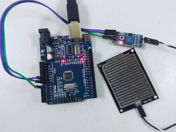
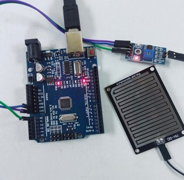
Fig: signal LED of the module is OFF when there are no water drops on the sensor plate
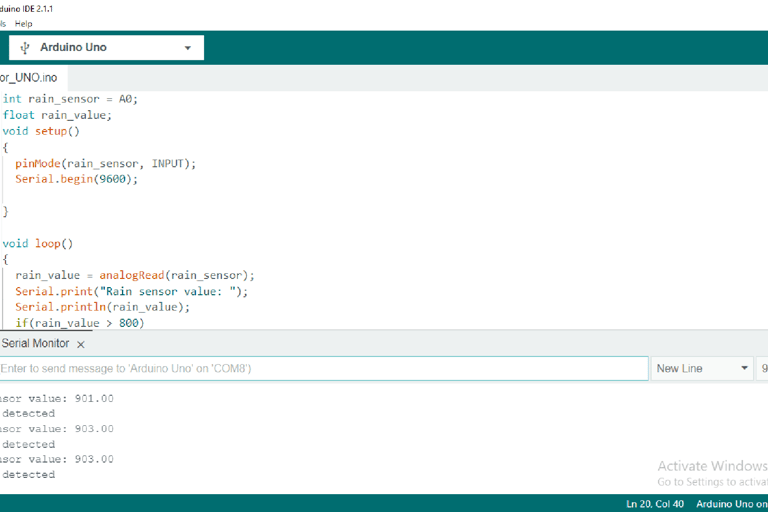
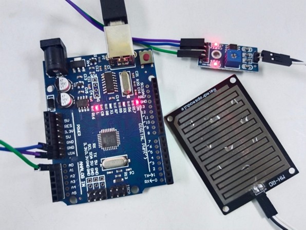
Fig: serial monitor display of analog value with no rain when sensor has no water drops on it
Fig: signal LED of the module is ON when there are few water drops on the sensor plate

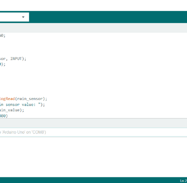
Fig: serial monitor display of analog value with medium when sensor has few water drops on it
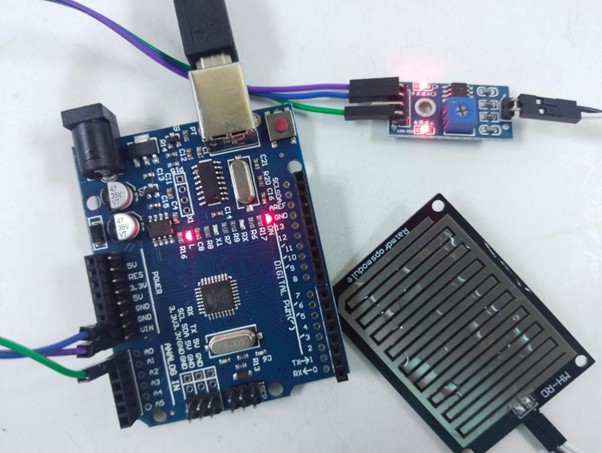
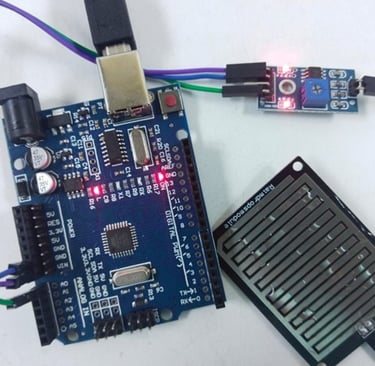
Fig: serial monitor display of analog value with medium when sensor has few water drops on it
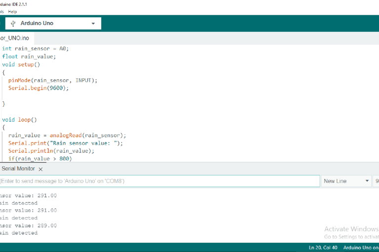
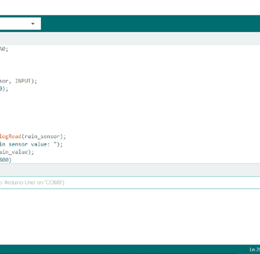
Fig: serial monitor display of analog value with heavy rain when sensor has many water drops on it
Fig: LED is OFF when there are no water drops on the sensor plate
Digital
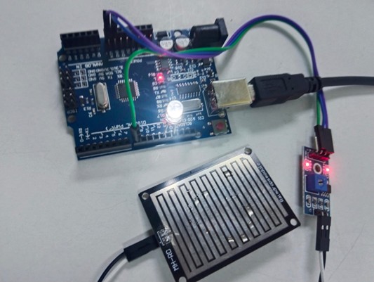
Fig: LED is OFF when there are no water drops on the sensor plate