
Interface the soil moisture sensor with an arduino
When designing a smart irrigation system or an automatic plant watering system, a soil moisture sensor is an essential component. With this sensor and an Arduino, we can create a system that waters plants only when necessary, preventing both overwatering and underwatering.
TRAINING
1/31/20256 min read
Introduction:
When designing a smart irrigation system or an automatic plant watering system, a soil moisture sensor is an essential component. With this sensor and an Arduino, we can create a system that waters plants only when necessary, preventing both overwatering and underwatering.
In this guide, we will interface the soil moisture sensor with an Arduino to measure the volumetric water content in the soil. The sensor is capable of providing both digital and analog outputs.
For digital output, we will display the soil status using an LED.
For analog output, we will use either the serial monitor or an LED with PWM to visualize the data.
Soil Moisture Sensor Pinout
The Soil Moisture Sensor features four pins: VCC, GND, Aout, and Dout. These pins allow you to obtain soil moisture data from the sensor. Here's the pinout for the Soil Moisture Sensor:
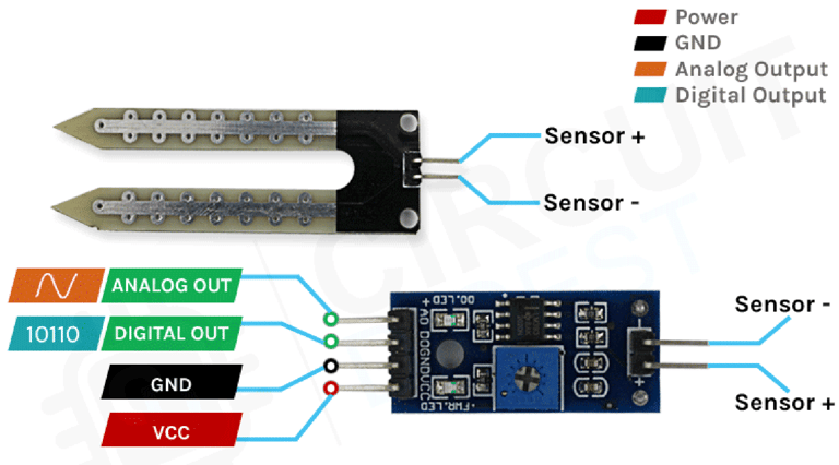
VCC is the power supply pin for the soil moisture sensor, which can be connected to either a 3.3V or 5V supply. Keep in mind that the analog output will vary depending on the supply voltage.
GND is the ground pin and should be connected to the ground pin of the Arduino.
DOUT is the digital output pin, where a low signal indicates appropriate soil moisture, while a high signal indicates low soil moisture.
AOUT is the analog output pin, providing a signal between VCC and ground.
How the Soil Moisture Sensor Works
The operation of the soil moisture sensor is simple and easy to understand. You simply insert the fork-shaped conductive probe into the soil. This probe contains two exposed conductive plates that act as a variable resistor, with the resistance changing based on the soil's water content.
The resistance of the probe is inversely proportional to the soil moisture level. When the soil has more water, the conductivity improves, leading to lower resistance. Conversely, when the soil has less water, the conductivity decreases, resulting in higher resistance. The sensor produces an output voltage based on this resistance, which can be used to determine the moisture level.
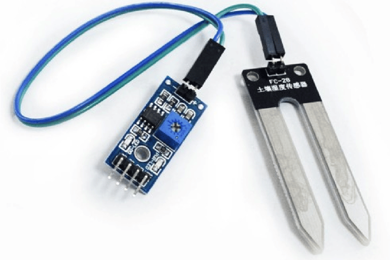
Soil Moisture Sensor - Components
The soil moisture sensor consists of two main parts: the sensor probe and the electronic module. The module processes the data received from the probe, which is then analyzed by a microcontroller like Arduino to provide the final output.
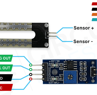
The Soil Moisture Sensor Probe
As mentioned earlier, the sensor includes a fork-shaped probe with two large exposed conductive pads. This probe functions like a variable potentiometer, and its value can be read by a microcontroller such as Arduino.
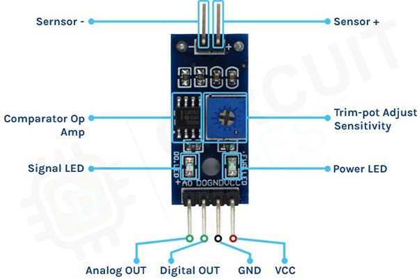
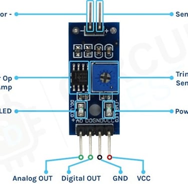
The Soil Moisture Sensor Module
The soil moisture sensor module is designed to convert the incoming analog signal from the probe into a digital signal. This module allows the sensor to function without requiring support from a microcontroller. It features two signal input pins for connecting the probe, along with four additional pins—two for VCC and GND, and the other two for Digital Output and Analog Output.
The module includes a high-precision comparator, the LM393, which digitizes the analog signal from the sensor probe. Additionally, it has a built-in potentiometer that allows for sensitivity adjustment of the digital output. The purpose of the potentiometer is to set a threshold: when the moisture level surpasses this threshold, the module outputs a LOW signal, and when it is below the threshold, it outputs HIGH. This functionality is particularly useful as it enables you to trigger actions, such as starting a water pump, when a certain moisture level is reached.
For optimal results, soil moisture sensors should be placed at various depths and locations within the field. Typically, sensors are positioned in pairs at one-third and two-thirds of the crop root zone depth, and at multiple locations in the field, ideally away from high points, depressions, and slopes.
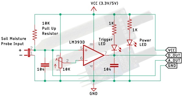
Circuit Diagram for Soil Moisture Sensor Module
The circuit schematic for the soil moisture sensor module is straightforward and requires only a few common components to build. If you don’t have a pre-assembled module but want to test your project, this schematic will be helpful.
In the schematic, you'll find an LM393 op-amp, a low-power, low-offset voltage operational amplifier that can be powered with either a 3.3V or 5V supply. Note that the analog output voltage of the sensor depends on the input voltage. The primary function of this op-amp is to convert the analog signal from the sensor probe into a digital signal.
Additionally, there’s a 10K potentiometer, which is used to set a reference voltage for the op-amp. When the sensor's input voltage falls below the threshold set by the potentiometer, the op-amp output goes low. The circuit also includes two LEDs: one for power indication and another as a trigger LED. The power LED lights up when the board is powered, while the trigger LED illuminates when the moisture level reaches the set threshold. This is the basic operation of the circuit.
Arduino Soil Moisture Sensor Circuit – Connection Diagram
Now that we understand how the soil moisture sensor works, we can proceed with connecting the necessary wires to the Arduino UNO board. This section will be divided into two parts: one for the analog output and another for the digital output. Let’s start with the analog circuitry.
Soil Moisture Sensor - Analog Output
To use the sensor, the first step is to provide power. For this, we’ll connect the 5V and GND pins of the Arduino UNO board to the sensor.
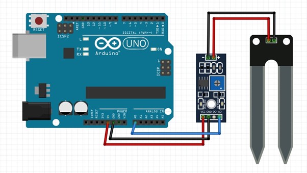
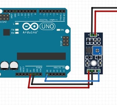
As shown in the above arduino soil moisture sensor circuit diagram the analog out pin of the sensor is connected to the A0 pin of the Arduino UNO board, finally, the ground is connect to the sensor.
Soil Moisture Sensor - Digital Output:
For the digital interface part, we are also using the +5V and Ground from the Arduino to power the sensor module.
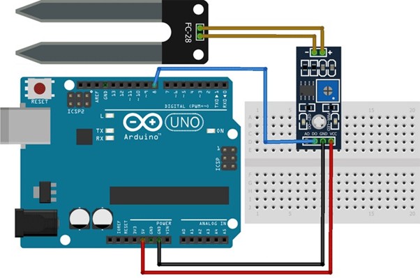
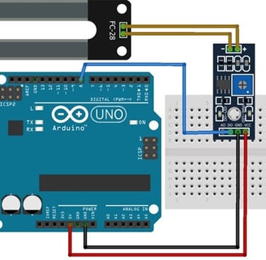
Connecting a soil moisture sensor to an Arduino or any other microcontroller is straightforward. Since the sensor provides both analog and digital signals, processing these signals is quite simple.
Arduino Soil Moisture Sensor Code
The code for the Arduino-based soil moisture sensor is simple and easy to understand. It primarily reads the analog data from the sensor and displays it on the serial monitor. Keep in mind that we are only processing the analog data from the sensor; for digital data, you can observe the onboard LED on the module, which lights up accordingly.
Analog code
int moisture_reading, moisture_percentage;//variables to store analog value and moisture percentage int SM_pin = A0;//connect A0 to sensor output A0 void setup()
{
Serial.begin(9600); } void loop() {
moisture_reading = analogRead(SM_pin); //reads the analog values from the sensor and stores in the variable Serial.print("Analog value: ");// prints on serial monitor Serial.println(moisture_reading);// prints analog values
moisture_percentage = map(moisture_reading, 480, 1023, 100, 0); //480 is calibrated value - always calibrate for new sensor Serial.print("Soil moisture:");//prints on serial monitor
Serial.print(moisture_percentage);//prints the moisture percentage Serial.println(" %"); delay(1000); }
Digital code
int ledPin=12; // initialising the pin 12 as the led pin
int sensorPin=8; // initialising pin 8 as the sensor output pin boolean val =1; void setup(){
pinMode(ledPin, OUTPUT); // set arduino pin to output mode pinMode(sensorPin, INPUT); // set arduino pin to input mode } void loop () {
val =digitalRead(sensorPin);//read the sensor pin with the digitalRead() function and store the value to the val variable.
if (val==LOW) // when the sensor detects a signal above the threshold value, LED flashes { digitalWrite(ledPin, HIGH); //LED turns ON delay(1000); } else { digitalWrite(ledPin, LOW);//LED turns OFF }
}
Working of the Soil Moisture Sensor Module
Analog
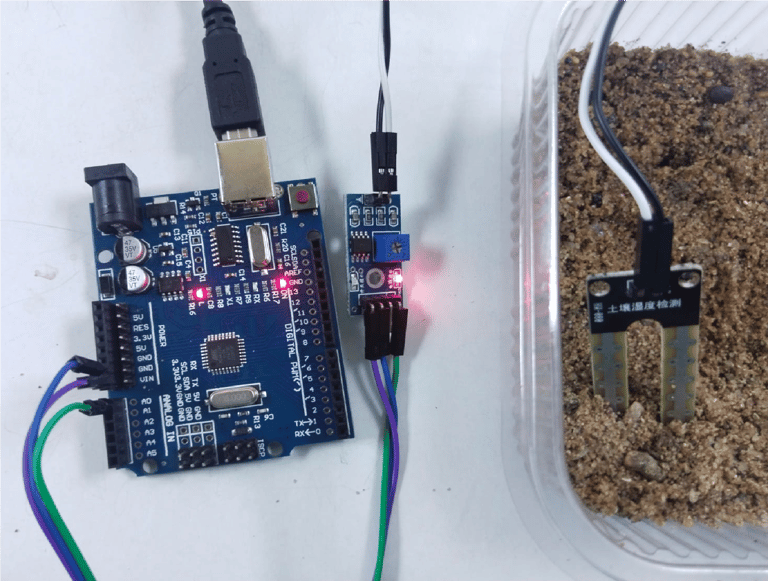
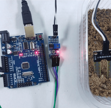
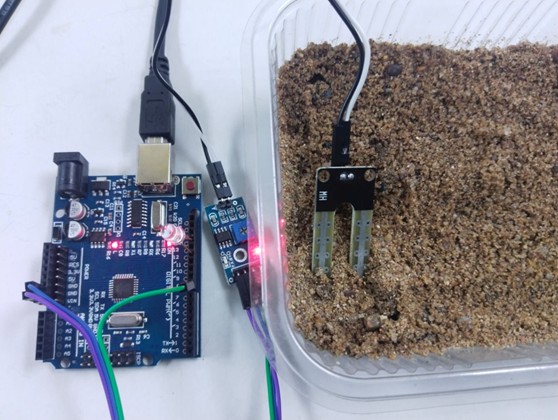
Fig: signal LED is OFF when sensor is placed in the dry soil
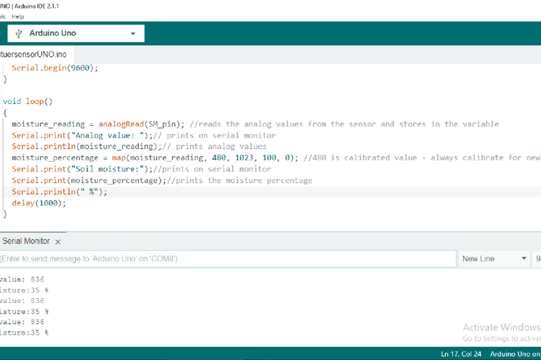
Fig: serial monitor display of analog value with 35% moisture when sensor is placed in the dry soil
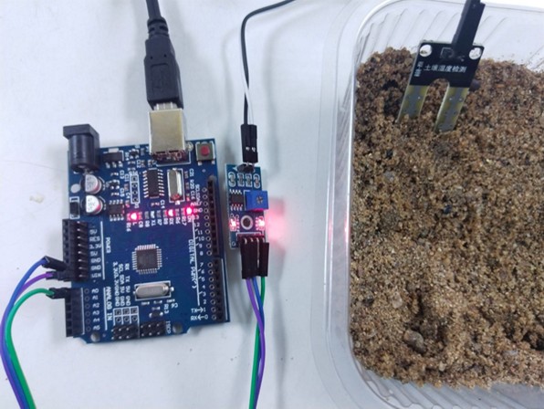
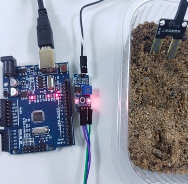
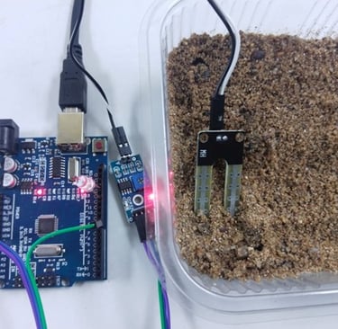
Fig: signal LED is ON when sensor is placed in the wet soil
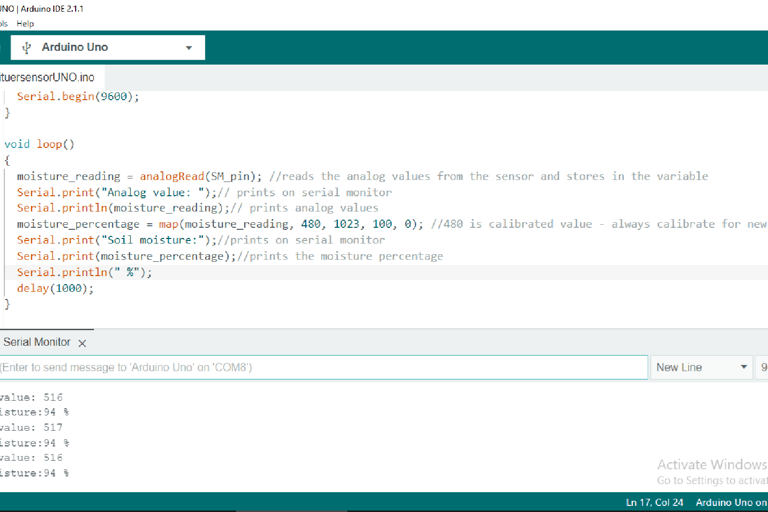
Fig: serial monitor display of analog value with 94% moisture when sensor is placed in the wet soil
LED is OFF when sensor is placed in the dry soil
Digital
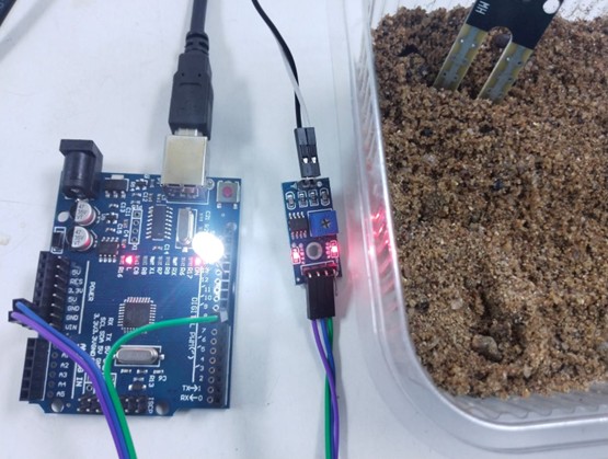
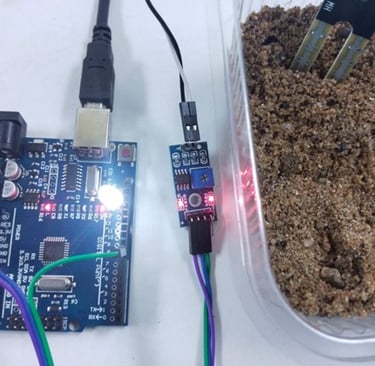
Fig: LED is ON when sensor is placed in the wet soil