
Interfacing Flame Sensor with Arduino
Blog post description.
TRAINING
2/1/20253 min read
Introduction:
Fire can cause significant damage, and detecting it early is crucial to prevent casualties and minimize destruction. By detecting fire promptly, we can provide warnings and even activate automatic fire suppression systems. Fire detection can be achieved through various methods, such as temperature change detection and smoke detection. Among these, detecting temperature changes is often more accurate, as some fires may not produce detectable smoke. However, temperature measurements alone can be unreliable, as they might only indicate a fire when it's already too late. To address this, we can detect thermal radiation instead of relying solely on temperature variation. The most cost-effective and simple way to detect thermal radiation is by using a flame sensor. In this tutorial, we will learn how to interface a flame sensor module with an Arduino.
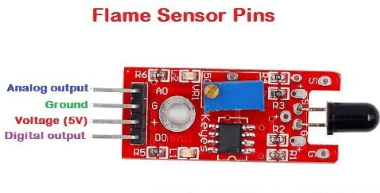
Flame Sensor Module Pinout
The flame sensor module consists of four pins: two for power and two for signal. The pinout of the module is as follows:
VCC: Provides power to the module; connect this pin to the 5V pin of the Arduino.
GND: Ground; connect this pin to the ground (GND) pin of the Arduino.
DO (Digital Output): Digital output pin for flame detection.
AO (Analog Output): Analog output pin for flame detection.
Flame Sensor Module Components:
The flame sensor module contains very few components, including an IR photodiode, an LM393 comparator IC, and several passive components. The power LED lights up when the module is powered, and the D0 LED turns off when a flame is detected. The sensitivity of the sensor can be adjusted using the onboard trimmer resistor.
Flame Sensor Module Circuit Diagram:
The schematic for the flame sensor module is shown below. As mentioned, the module has a simple design with minimal components. The primary components are the IR photodiode and the comparator circuit.
The operation of the flame sensor module is based on a simple principle: a hot object emits infrared (IR) radiation, and a flame or fire emits a significant amount of this radiation. The sensor detects this IR radiation using an infrared photodiode. The photodiode's conductivity changes depending on the amount of IR radiation it detects. An LM393 comparator is used to compare the detected radiation, and once the radiation reaches a threshold, the digital output changes.
We can also use the analog output to measure the intensity of the IR radiation. This output is directly taken from the photodiode's terminal. The onboard D0 LED will indicate the presence of a flame when it is detected. Additionally, the sensitivity can be adjusted using the onboard variable resistor, which helps in reducing false triggers.
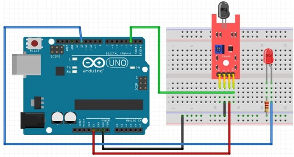
Arduino Flame Sensor Interfacing Circuit Diagram:
Now that we understand how the flame sensor works, let's connect the sensor to the Arduino and write the code to retrieve data from it. The circuit diagram for interfacing the flame sensor with Arduino is shown below. The connections are simple and require just three wires:
Connect the VCC and GND of the flame sensor to the 5V and GND pins of the Arduino.
Connect the D0 pin to digital pin 2 of the Arduino. We will monitor this pin to detect the fire.
Arduino Flame Sensor Code:
The code to interface the flame sensor with Arduino is straightforward and easy to follow. We simply need to define the pin to which the sensor is connected on the Arduino. After that, we can monitor the status of this pin to detect the presence of a flame.
int led_pin = 12 ;// initialising the pin 9 as the led pin
int flame_sensor_pin = 2 ;// initialising pin 12 as the sensor output pin
int flame_pin = HIGH ; // state of sensor
void setup ( ) {
pinMode ( led_pin , OUTPUT ); // declaring led pin as output pin
pinMode ( flame_sensor_pin , INPUT ); // declaring sensor pin as input pin for Arduino
Serial.begin ( 9600 );// setting baud rate at 9600
}
void loop ( ) {
flame_pin = digitalRead (flame_sensor_pin) ; // reading from the sensor
if (flame_pin == LOW ) // applying condition
{
Serial.println ( " FLAME , FLAME , FLAME " ) ;
digitalWrite ( led_pin , HIGH ) ;// if state is high, then turn high the led } else
{
Serial.println ( " no flame " ) ;
digitalWrite ( led_pin , LOW ) ; // otherwise turn it low
}
delay(1000);
}
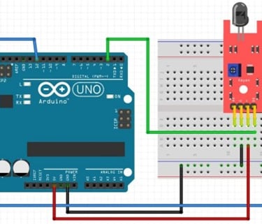
Working
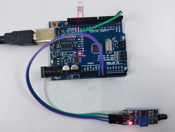
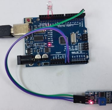
Fig: LED is OFF when there is no flame
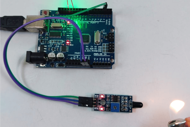
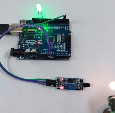
Fig: LED is ON when there is flame near sensor