
Interfacing IR sensor , LED and buzzer with arduino UNO
In this project, we will use basic components like an Arduino Uno (or any other microcontroller), an LED, a buzzer, and a few additional parts. There are various types of IR sensors available in the market, ranging from basic ones to advanced arrays designed for specific purposes. The basic function of these sensors is the same, but an array sensor provides an average reading from 4 to 5 individual IR sensors, leading to more accurate and error-free values.
TRAINING
2/1/20254 min read
Introduction:
How to Make an Obstacle Detector Using an IR Sensor with Arduino:
In this project, we will use basic components like an Arduino Uno (or any other microcontroller), an LED, a buzzer, and a few additional parts. There are various types of IR sensors available in the market, ranging from basic ones to advanced arrays designed for specific purposes. The basic function of these sensors is the same, but an array sensor provides an average reading from 4 to 5 individual IR sensors, leading to more accurate and error-free values.
An IR sensor consists of two LEDs: a white one that acts as an Infrared Light transmitter, and a black one that functions as an Infrared Light receiver. As their names suggest, their roles are straightforward. The sensor is built around the LM358 IC, which is similar to the LM393 IC that you may already be familiar with.
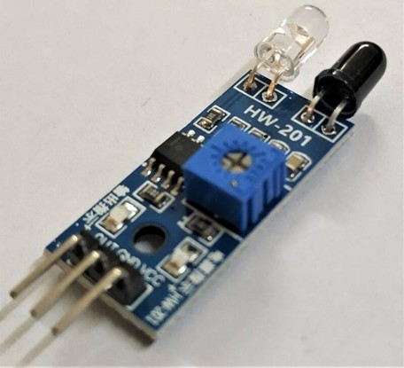
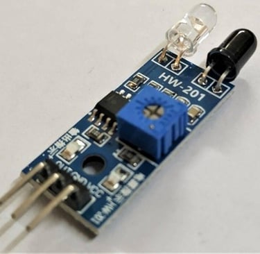

The IR sensor also features an onboard power LED and a status LED that blinks whenever the sensor detects or receives infrared light reflected back from the emitter.
Additionally, you can fine-tune the sensor's values using a potentiometer on the sensor's PCB, allowing for adjustment of the IR sensor's sensitivity.
Note: The sensor's performance depends on factors such as the distance of the emitted light, the reflecting surface, and the receiver. Additionally, dark or black surfaces tend to absorb infrared light, which can prevent the sensor from working correctly on those surfaces.
Components Required for IR Sensor with Arduino:
Arduino UNO
USB cable for uploading the code
IR sensor
Buzzer and LED
Jumper wires and breadboard
220-ohm resistor
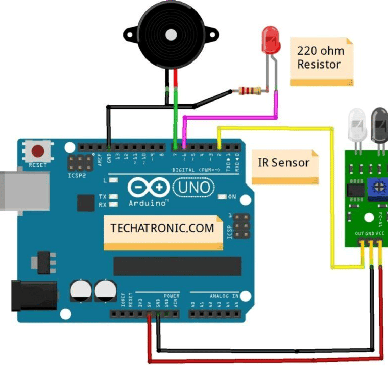
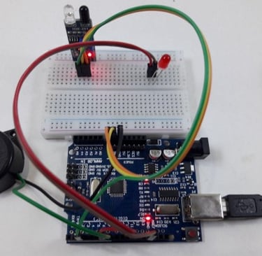
IR Sensor with Arduino Circuit Diagram:
Below is the circuit diagram for connecting the digital output of the IR sensor to the Arduino.
Begin by establishing power connections on the breadboard. Connect VCC (5V) from the Arduino to the + rail on the breadboard and GND to the - rail using jumper wires.
Place the IR sensor on the breadboard and connect its VCC and GND pins to the corresponding power rails.
Connect the D0 pin of the sensor to digital pin 2 of the Arduino.
Attach an LED to the breadboard:
Connect the positive leg (anode) of the LED to digital pin 13 of the Arduino.
Connect the negative leg (cathode) to GND in series with a 220-ohm resistor.
Add a buzzer for additional feedback:
Connect the negative (-) terminal of the buzzer to GND on the breadboard.
Connect the positive (+) terminal of the buzzer to digital pin 12 of the Arduino.
This setup ensures that both the LED and buzzer will activate when an obstacle is detected by the IR sensor.
IR Sensor with Arduino Code:-
int val = 1 ;
void setup() {
Serial.begin(9600); // sensor baud rate
pinMode(2,INPUT); // IR sensor output pin connected and set the pin to input mode
pinMode(6,OUTPUT); // LED connected pin 6 and set the pin to output mode
pinMode(7,OUTPUT); // BUZZER connected pin 7 and set the pin to output mode
}
void loop() {
val = digitalRead(2); // IR sensor output pin connected
Serial.println(val); // see the value in serial monitor in Arduino IDE
delay(500);
if(val == 0 ) // the output of the sensor is high that means no motion is detected {
digitalWrite(6,HIGH); // LED ON
digitalWrite(7,HIGH); // BUZZER ON
}
else { digitalWrite(6,LOW); // LED OFF
digitalWrite(7,LOW); // BUZZER OFF
}
}
Working of IR Sensor with Arduino:
In the setup section of the code, we define the pin to which the sensor is connected and specify its type (input or output). Additionally, we initialize the pins for both the LED and buzzer to ensure they function correctly.
In the loop section, the program continuously reads the digital signal from pin 2 of the microcontroller. Based on the received value (either 1 or 0), the system applies conditional logic to turn the LED and buzzer on or off accordingly.
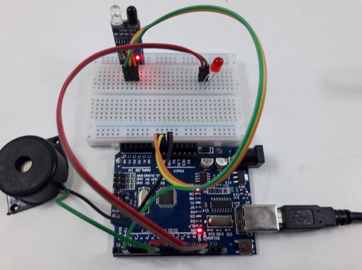
Fig: led and buzzer are ON when motion is detected
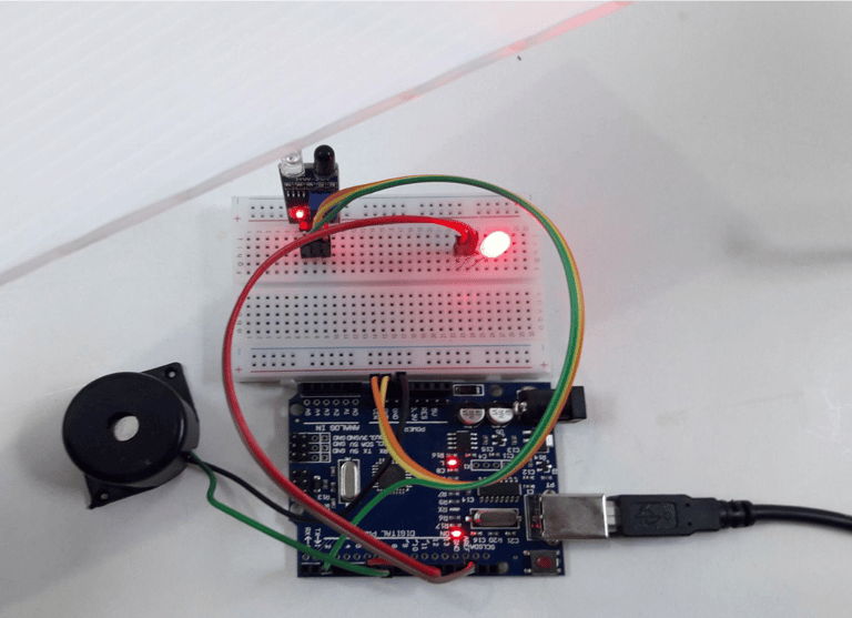
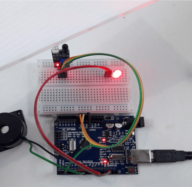
Fig: led and buzzer are ON when motion is detected
Advantages of IR Sensors
IR sensors offer several benefits, including:
Low power consumption
Reliable motion detection regardless of lighting conditions
Non-contact operation, allowing detection without physical contact
No data leakage, as infrared rays travel in a specific direction
Resistant to oxidation and corrosion, ensuring durability
Strong noise immunity, making them less susceptible to interference
Disadvantages of IR Sensors
Despite their advantages, IR sensors have some limitations:
Require a clear line of sight for accurate detection
Limited range, restricting their application in large areas
Susceptible to environmental factors such as fog, rain, and dust
Lower data transmission rate compared to other wireless communication methods
Applications of IR Sensors
IR sensors come in various types, each suited for different applications:
Speed sensors – Used for synchronizing the speed of multiple motors.
Temperature sensors – Applied in industrial temperature control.
PIR sensors – Commonly used in automatic door-opening systems.
Ultrasonic sensors – Utilized for distance measurement.
IR sensors play a crucial role in sensor-based projects and electronic devices designed for temperature measurement and automation.