
Interfacing IR sensor with arduino UNO
An Infrared (IR) Proximity Sensor is an electronic device that emits infrared light to detect certain aspects of its surroundings, primarily used for motion detection. As a passive sensor, it can only measure infrared radiation and does not emit any signals for detection. This type of sensor is widely used in the electronics industry, particularly in applications like obstacle avoidance robots and other proximity-based detection systems.
TRAINING
2/1/20255 min read
Introduction
An Infrared (IR) Proximity Sensor is an electronic device that emits infrared light to detect certain aspects of its surroundings, primarily used for motion detection. As a passive sensor, it can only measure infrared radiation and does not emit any signals for detection. This type of sensor is widely used in the electronics industry, particularly in applications like obstacle avoidance robots and other proximity-based detection systems.
IR Sensor Pinout
The IR sensor features a 3-pin connector for external interfacing. The pin connections are as follows:
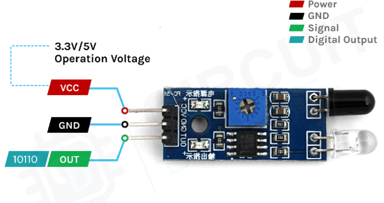
VCC – The power supply pin for the IR sensor, which should be connected to the 5V pin on the Arduino.
OUT – A 5V TTL logic output where:
LOW (0V) indicates no motion is detected.
HIGH (5V) means motion is detected.
GND – Connects to the ground (GND) pin of the Arduino.
How an IR Motion Sensor Module Works
The IR sensor module operates using two primary components:
IR Transmitter Section – Consists of an IR LED that emits infrared light.
IR Receiver Section – Uses a photodiode to detect the reflected infrared signal. The received signal undergoes processing and conditioning before being converted into a digital output.
When power is applied, the Infrared LED emits infrared light, which propagates through the air and reflects off nearby objects. The photodiode sensor detects the reflected light, and based on the intensity of the reflection, the sensor determines the object's proximity:
Stronger reflection – Indicates the object is close to the sensor.
Weaker reflection – Indicates the object is farther away.
If the sensor detects an object within range, it sends a LOW signal through the output pin, which can be read by an Arduino or any other microcontroller to trigger a specific action.
One useful feature of this module is its built-in LEDs:
One power LED turns on when the sensor is powered.
Another status LED lights up when an object is detected.
IR Motion Sensor Module – Features
This sensor is widely used in Arduino projects for proximity detection and obstacle avoidance robots. It is popular among beginners due to its:
Low power consumption
Affordable cost
Durability
Adjustable sensitivity
Wide sensing range that can be fine-tuned using the onboard potentiometer
IR Motion Sensor Module Overview
This sensor consists of three pins:
VCC – Power supply pin
GND – Ground connection
Sense/Data Pin – Outputs the detection signal
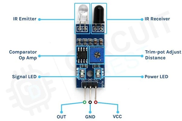
Key Components and Features
Onboard LEDs:
Power LED – Lights up when the sensor is powered.
Signal LED – Activates when the sensor detects motion.
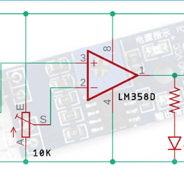
Comparator Op-Amp – Converts the analog signal from the photodiode into a digital signal.
Sensitivity Adjustment Potentiometer – Allows fine-tuning of the sensor's detection sensitivity.
IR Emitting LED & Photodiode Pair – Forms the core detection system, enabling infrared proximity sensing.
Circuit Diagram for IR Motion Sensor Module
The schematic of the IR Motion Sensor Module is straightforward and consists of only a few common electronic components. If a prebuilt module is unavailable, you can still construct and test the circuit using the provided schematic.
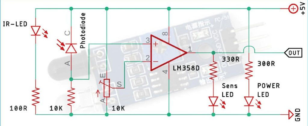
Understanding the IR Sensor Schematic
The circuit consists of:
IR LED (Transmitter) – Emits infrared light.
Photodiode (Receiver) – Detects the reflected infrared light from nearby objects.
LM358 Op-Amp – Compares the received signal and generates an output.
Potentiometer – Adjusts the sensor's sensitivity or the detection range.
When an object is placed in front of the sensor, the infrared light reflects off the object and is detected by the photodiode. The intensity of the reflected light determines the object's distance. The LM358 Op-Amp processes this signal and produces a digital output based on the threshold set using the potentiometer.
Connecting IR Sensor to Arduino UNO
Now that we understand how an IR sensor functions, we can proceed with wiring it to an Arduino UNO as illustrated in the connection diagram.
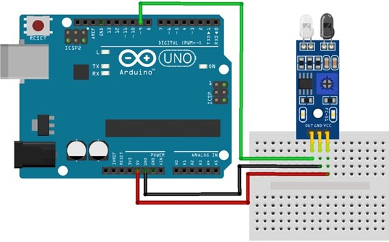
Connecting the IR sensor to any microcontroller is really simple. As we know this sensor outputs a digital signal and processing this signal is very easy. There exist two methods to do so: first, you can always check the port in an infinite loop to see when the port changes its state from high to low, or the other way is to do it with an interrupt if you are making a complicated project the interrupt method is recommended. Power the IR with 5V or 3.3V and connect ground to ground. Then connect the output to a digital pin D9. We have just used a Male to Female Jumper wire to connect the IR sensor module with the Arduino board as shown below in the working.
With that, we’re now ready to upload some code and get the IR Motion Sensor working.
Code for Interfacing IR Motion Sensor Module with Arduino
int IRsensor = 9;// connect out of ir sensor to pin 9 of arduino void setup() {
pinMode(IRsensor, INPUT); // set arduino pin to input mode Serial.begin(9600); pinMode(LED_BUILTIN, OUTPUT); // set led builtin to output mode } void loop() { int IR = digitalRead(IRsensor); //read the sensor pin with the digitalRead() function and store the value to the IR variable.
if (IR == 1) // the output of the sensor is high that means no motion is detected {
digitalWrite(LED_BUILTIN, LOW); //LED OFF Serial.println("No obstacle detected..."); // prints in the serial monitor }
if (IR == 0) // the output of the sensor is low that means motion is detected {
digitalWrite(LED_BUILTIN, HIGH); // LED ON Serial.println("Obstacle detected..."); // prints in the serial monitor } delay(1000); }
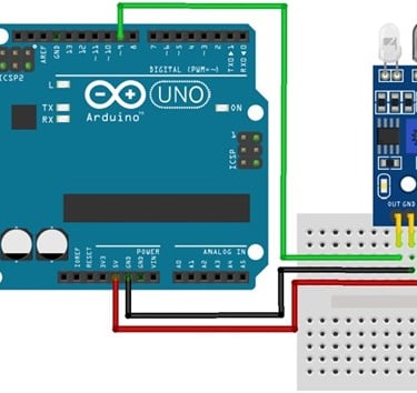
Working of the IR Motion Sensor Module
you can notice the LED turn on both on the module and on the Arduino board when there is an obstacle.
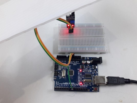
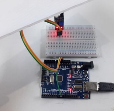
Fig : builtin led of arduino and sensor are ON when motion is detected
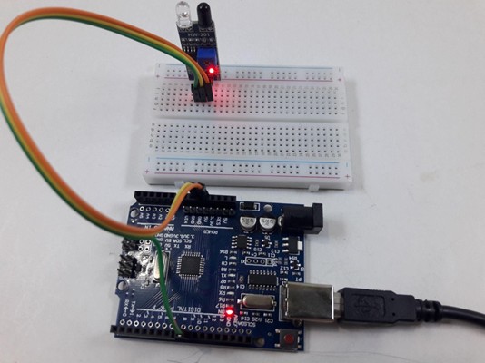
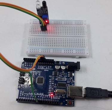
Fig: built in led of arduino and sensor are OFF when there is no motion detected
Advantages of IR Sensors
IR sensors offer several benefits, including:
Low Power Consumption – Operates efficiently with minimal energy.
Reliable Detection – Can detect motion effectively in both light and dark conditions.
Non-Contact Sensing – Detects objects without physical contact.
Secure Data Transmission – No data leakage due to directional infrared rays.
Resistant to Environmental Factors – Unaffected by oxidation and corrosion.
Strong Noise Immunity – Less prone to signal interference.
Disadvantages of IR Sensors
Despite their advantages, IR sensors have some limitations:
Line-of-Sight Requirement – Objects must be directly in the sensor's field of view.
Limited Range – Detection distance is relatively short.
Environmental Interference – Performance may be affected by fog, rain, dust, etc.
Lower Data Transmission Rate – Not suitable for high-speed communication.
Applications of IR Sensors
IR sensors are classified based on their applications. Some common uses include:
Speed Sensors – Used for synchronizing the speed of multiple motors.
Temperature Sensors – Employed in industrial temperature control systems.
PIR Sensors – Used in automatic door opening systems.
Ultrasonic Sensors – Applied in distance measurement systems.
IR sensors play a crucial role in sensor-based projects and are widely integrated into electronic devices for temperature measurement and other applications.