
Interfacing MAX30100 Pulse Oximeter with Arduino
The MAX30100 is an I2C-compatible, low-power biometric sensor designed for pulse oximetry and heart rate monitoring. It is ideal for students, hobbyists, engineers, manufacturers, and developers looking to integrate real-time heart rate data into their projects.
TRAINING
2/1/20256 min read
Introduction:
The MAX30100 is an I2C-compatible, low-power biometric sensor designed for pulse oximetry and heart rate monitoring. It is ideal for students, hobbyists, engineers, manufacturers, and developers looking to integrate real-time heart rate data into their projects.
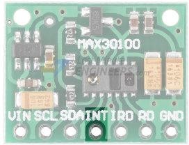
MAX30100 Module Hardware Overview:
The module is built around the MAX30100 IC, an advanced pulse oximeter and heart rate sensor from Analog Devices. It integrates two LEDs, a photodetector, optimized optical components, and a low-noise analog signal processor to accurately measure SpO2 (blood oxygen saturation) and heart rate (HR).
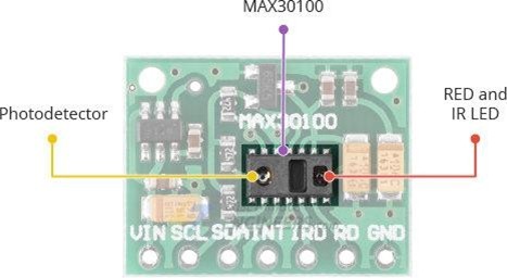
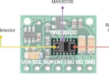
On the right side of the MAX30100 module, there are two LEDs—a RED LED and an IR (Infrared) LED. On the left, there is a highly sensitive photodetector. The sensor operates by emitting light from one LED at a time and measuring the amount of reflected light detected. Based on the detected signal patterns, it can determine blood oxygen levels (SpO2) and heart rate.
Power Requirements:
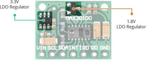
The MAX30100 requires two different supply voltages: 1.8V for the IC itself and 3.3V for the RED and IR LEDs. To accommodate this, the module includes built-in 1.8V and 3.3V voltage regulators, making it compatible with microcontrollers operating at 5V, 3.3V, or even 1.8V logic levels
One of the key features of the MAX30100 is its low power consumption. It uses less than 600μA during measurement, and in standby mode, it consumes only 0.7μA. This makes it ideal for battery-powered devices such as handsets, wearables, or smartwatches.
On-Chip Temperature Sensor
The MAX30100 includes an on-chip temperature sensor, which helps compensate for environmental changes and calibrate measurements. This temperature sensor is fairly accurate, measuring the 'die temperature' within the range of -40°C to +85°C, with an accuracy of ±1°C.
I2C Interface
The module uses a simple two-wire I2C interface for communication with a microcontroller. It has a fixed I2C address: 0xAEHEX for write operations and 0xAFHEX for read operations.
FIFO Buffer
The MAX30100 features a FIFO (First In, First Out) buffer to store data samples. This buffer has a memory capacity of 16 samples, meaning it can hold up to 16 SpO2 and heart rate samples. The FIFO buffer helps offload the microcontroller from constantly reading new data samples, thus saving system power.
Interrupts
The MAX30100 can be configured to generate interrupts, enabling the host microcontroller to perform other tasks while the sensor collects data. Interrupts can be triggered from five different sources:
Power Ready: Triggers on power-up or after a brownout condition.
SpO2 Data Ready: Triggers after each SpO2 data sample is collected.
Heart Rate Data Ready: Triggers after each heart rate data sample is collected.
Temperature Ready: Triggers when an internal die temperature conversion is completed.
FIFO Almost Full: Triggers when the FIFO is nearly full and future data might be lost.

The INT line is an open-drain, meaning it is pulled HIGH by an onboard resistor. When an interrupt occurs, the INT pin goes LOW and remains LOW until the interrupt is cleared.
Technical Specifications
Here are the key technical specifications of the MAX30100:
Power Supply: 3.3V to 5.5V
Current Draw: ~600μA (during measurements), ~0.7μA (during standby mode)
Red LED Wavelength: 660nm
IR LED Wavelength: 880nm
Temperature Range: -40˚C to +85˚C
Temperature Accuracy: ±1˚C
How the MAX30100 Pulse Oximeter and Heart Rate Sensor Works
The MAX30100, like any optical pulse oximeter and heart-rate sensor, consists of a pair of high-intensity LEDs (one Red and one Infrared) and a photodetector. The Red LED operates at a wavelength of 660nm, while the IR LED operates at 880nm.
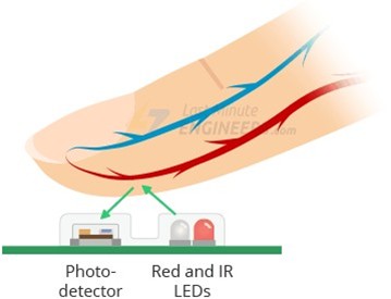


The MAX30100 operates by shining both red and infrared light onto the finger, earlobe, or any area where the skin is thin enough for both lights to penetrate the tissue. It then measures the amount of reflected light using a photodetector. This technique of detecting pulse through light is known as Photoplethysmogram (PPG).
The operation of the MAX30100 can be broken down into two main functions: Heart Rate Measurement and Pulse Oximetry (measuring blood oxygen levels).
Heart Rate Measurement
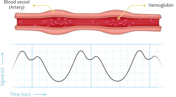
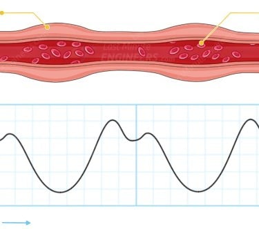
Oxygenated hemoglobin (HbO2) in the arterial blood absorbs infrared (IR) light. The more oxygenated the blood (the redder it is), the greater the absorption of IR light. As the blood is pumped through the finger with each heartbeat, the amount of reflected light changes, producing a fluctuating waveform at the photodetector’s output. By continuously shining light and taking photodetector readings, the sensor is able to calculate the heart rate (HR) pulse.
Pulse Oximetry
Pulse oximetry relies on the principle that the absorption of red and infrared (IR) light changes depending on the oxygen level in your blood. The graph below shows the absorption spectrum of both oxygenated hemoglobin (HbO2) and deoxygenated hemoglobin (Hb).
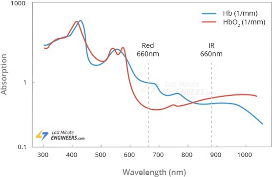
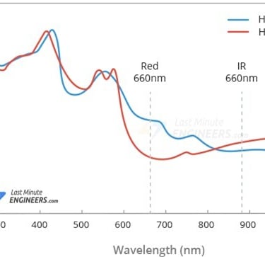
As shown in the graph, deoxygenated blood absorbs more red light (660nm), while oxygenated blood absorbs more infrared light (880nm). By calculating the ratio of the infrared and red light received by the photodetector, the oxygen saturation level (SpO2) in the blood can be determined.
Did You Know?
The technique of measuring hemoglobin oxygen saturation (HbO2) by analyzing the absorption of red and infrared light was first introduced in 1935 by German physician Karl Matthes. Initially, due to a lack of reliable photodetectors, the green light spectrum was used instead of infrared. However, as technology improved, infrared light replaced green light for more accurate measurements.
MAX30100 Module Pinout
The MAX30100 module exposes the following connections.
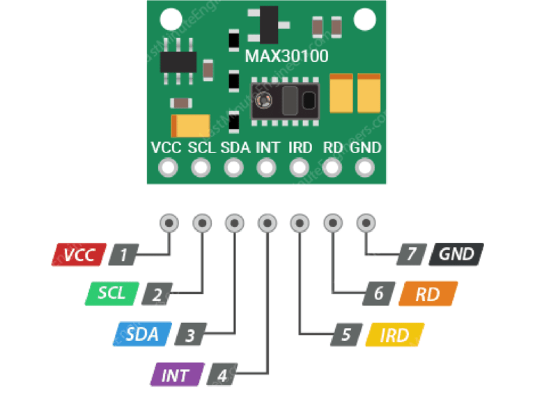
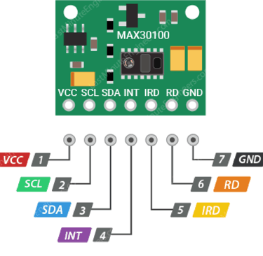
VIN: This is the power pin. You can connect it to either the 3.3V or 5V output from your Arduino.
SCL: The I2C clock pin, which connects to your Arduino’s I2C clock line.
SDA: The I2C data pin, which connects to your Arduino’s I2C data line.
INT: The MAX30100 can be configured to generate an interrupt for each pulse. This line is open-drain and is pulled HIGH by an onboard resistor. When an interrupt occurs, the INT pin goes LOW and remains LOW until the interrupt is cleared.
IRD: The MAX30100 has an integrated LED driver to control the IR LED pulses for SpO2 and heart rate measurements. You can use this pin if you want to drive the IR LED manually; otherwise, leave it unconnected.
RD: Similar to the IRD pin, this is used to drive the red LED. If you don’t want to control the red LED manually, leave it unconnected.
GND: This is the ground pin.
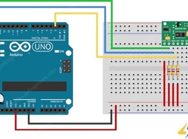
The wiring is the same as the first one; you just need to add external 4.7kΩ pullup resistors on the SCL, SDA and INT signal lines.
Our Evaluation:
We have tested both solutions and they work great. So try one which is easier for you to implement.
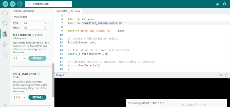
Library Installation
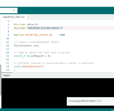
The code uses the MAX30100_PulseOximeter.h library. It can be downloaded from the Library Manager in the Arduino IDE and installed from there.
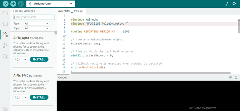
For that, open the Arduino IDE and go to Manage Libraries. Now search for MAX30100_PulseOximeter.h and install
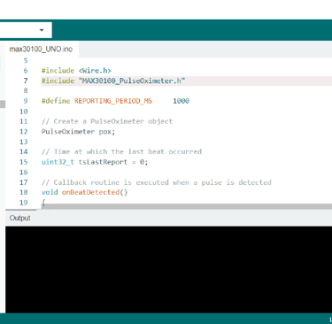
Code
#include <Wire.h> // library declaration
#include "MAX30100_PulseOximeter.h"// library for sensor
#define REPORTING_PERIOD_MS 1000 PulseOximeter pox;// Create a PulseOximeter object uint32_t tsLastReport = 0;// Time at which the last beat occurred void onBeatDetected()// Callback routine is executed when a pulse is detected {
Serial.println("Beat!"); } void setup() {
Serial.begin(9600); Serial.print("Initializing pulse oximeter.."); if (!pox.begin())// Initialize sensor { Serial.println("FAILED"); for(;;); } else
{
Serial.println("SUCCESS"); } pox.setIRLedCurrent(MAX30100_LED_CURR_7_6MA); // Configure sensor to use 7.6mA for LED drive pox.setOnBeatDetectedCallback(onBeatDetected);// Register a callback routine
} void loop() { pox.update();// Read from the sensor if (millis() - tsLastReport > REPORTING_PERIOD_MS) // Grab the updated heart rate and SpO2 levels {
Serial.print("Heart rate:");
Serial.print(pox.getHeartRate());
Serial.print("bpm / SpO2:");
Serial.print(pox.getSpO2());
Serial.println("%"); tsLastReport = millis(); }
}
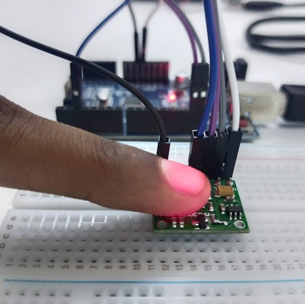
Working
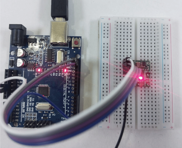
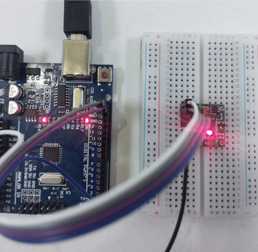
Fig: max30100 is turned ON after connecting according to the schematic diagram


Fig: serial monitor when no pulse is sensed
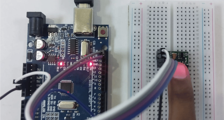
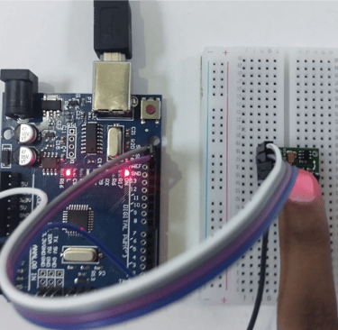
Fig: keep your finger on the light of the max30100 to get your pulse


Fig: serial monitor is displaying the heart rate