
Interfacing Mercury switch / Tilt sensor with Arduino UNO
The tilt sensor module consists of a tilt sensor and a potentiometer. When attached to an object, it can detect whether the object is tilted or not. In this lesson, we will explore how the tilt sensor module functions and how to use it with an Arduino board to sense tilt angles or movement.
TRAINING
2/1/20253 min read
Introduction
The tilt sensor module consists of a tilt sensor and a potentiometer. When attached to an object, it can detect whether the object is tilted or not. In this lesson, we will explore how the tilt sensor module functions and how to use it with an Arduino board to sense tilt angles or movement.
Components Required
Arduino UNO x 1
Tilt Sensor Module x 1
Jumper Wires
USB Cable x 1
PC x 1
About the Tilt Sensor Module
Tilt sensors are crucial in modern security alarm systems. These standalone sensors detect tilt angles or movements. Tilt sensors can be made using various technologies like mercury or roller balls and can be mounted through mechanical threading, magnets, or adhesives, depending on the surface they are attached to.
Features
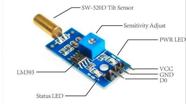
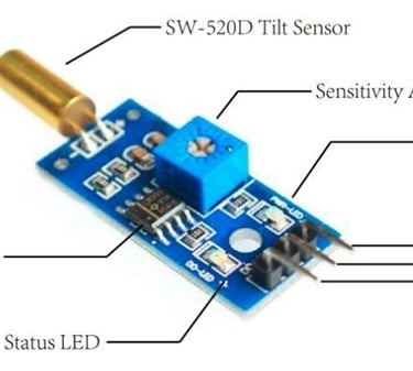
Utilizes a highly sensitive angle switch (SW-520D) as the sensor
Clean comparator output signal with good waveform and driving capacity (greater than 15mA)
Operating voltage of 5V
Digital switching output format (0 and 1)
Includes a fixed bolt hole for easy installation
Compact PCB size: 3.2cm x 1.4cm
Uses a wide voltage comparator, LM393
Recent technological advancements in tilt sensor manufacturing have enhanced accuracy, reduced costs, and extended lifespan. The SW-520D is a widely available roller-ball type tilt sensor that consists of two conductive poles and a free-moving conductive mass (ball), all housed in a single casing. When the sensor is tilted so that the ball rolls onto the poles, it short-circuits them, acting as a switch. Affordable microcontroller-compatible tilt sensor modules based on SW-520D are also available.
The electronics behind this module are usually based around the dual comparator chip LM393. It includes a tilt sensor, signal amplifier, standard 4-pin header, power indicator (to confirm proper power), and a status indicator that lights up when tilt is detected.
The module outputs a logic LOW when the sensor is tilted below the threshold angle and a logic HIGH when it is tilted above the threshold angle. The threshold angle typically ranges from 45 to 130 degrees. Additionally, the angular velocity can also influence the module's behavior, and it can even be used as a vibration sensor.
TILT SWITCH
In this project, we will use a tilt switch module along with an onboard LED connected to pin 13 of the Arduino. When the tilt switch outputs a low signal, the LED will turn on; otherwise, it will remain off.
Connections
Follow the circuit diagram below to build your setup.
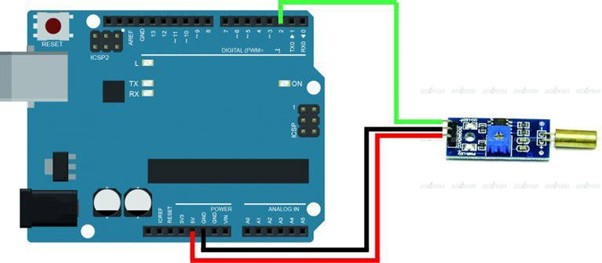
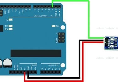
To connect the tilt sensor module to the Arduino, use appropriate jumper wires. Start by connecting the power supply lines: connect the VCC and GND of the module to the 5V and GND pins of the Arduino, respectively. Then, connect the digital output (DO) pin of the module to digital pin 2 (D2) on the Arduino. Power the entire setup using a 9V DC or USB source through the DC IN/USB socket on the Arduino board. Make sure the tilt switch is in an upright position.
Code Program
Once the hardware connections are complete, connect the Arduino board to your computer via the USB cable. The green power LED (labeled PWR) should light up. Open the Arduino IDE and select the correct board and port for your project. Finally, upload the following sketch to your Arduino.
const int sigPin = 2; // the number of the tilt switch pin const int ledPin = 13; // the number of the LED pin boolean sigState = 0; // variable for reading the tilt switch status void setup() { pinMode(ledPin, OUTPUT); // initialise the LED pin as an output pinMode(sigPin, INPUT); // initialise the tilt switch pin as an input } void loop() { sigState = digitalRead(sigPin);// read the state of the tilt switch value if (sigState == HIGH) { digitalWrite(ledPin, LOW); // turn LED on } else { digitalWrite(ledPin, HIGH); // turn LED off }
}
Working:
After the upload is complete, tilt the switch a few seconds later. When the switch tilts in either direction and the tilt angle and force meet the set conditions, the switch will be activated and output a low-level signal. This will turn the LED on. If the tilt condition is not met, the LED will remain off.
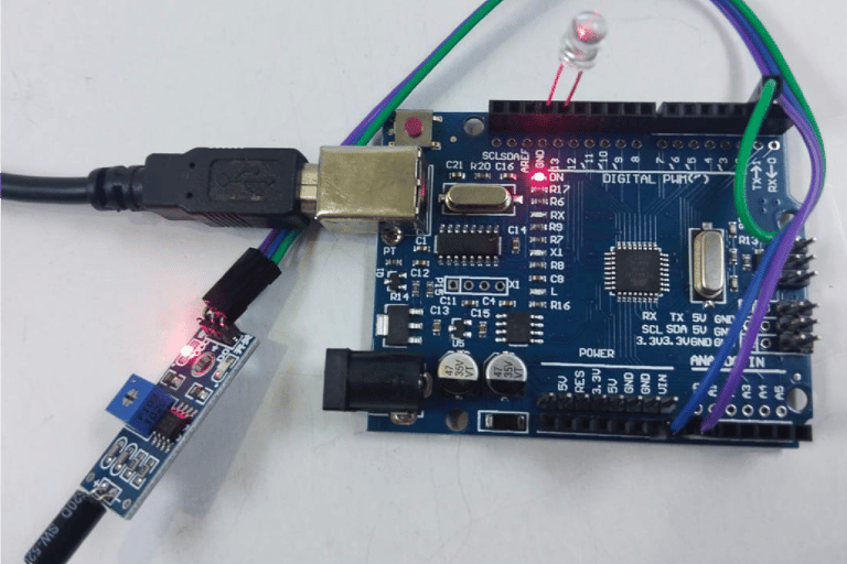
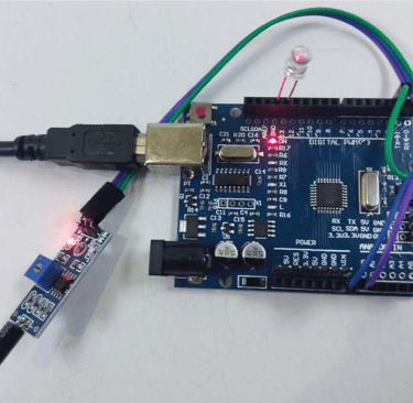
Fig: LED is OFF when sensor is not titled
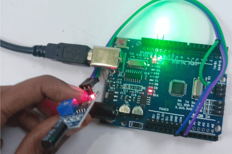
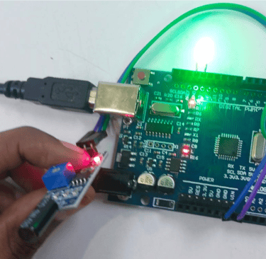
Fig: LED is ON when sensor is tilted