MQ-2 Combustible Gas and Smoke Sensor with arduino
Today, sensors are essential for ensuring the safety and security of various spaces like homes, offices, and apartments. They help detect hazards such as smoke, fire, or gas and alert the concerned individuals. In this article, we will focus on one such sensor commonly used in smoke and gas detectors: the MQ-2 Combustible Gas and Smoke Sensor. Despite its name, this sensor is capable of detecting not only smoke and gas, but also LPG, alcohol, propane, hydrogen, methane, and carbon monoxide. Let's explore how we can integrate this sensor into our projects to give them a "sense of smell."
TRAINING
1/31/20256 min read
Today, sensors are essential for ensuring the safety and security of various spaces like homes, offices, and apartments. They help detect hazards such as smoke, fire, or gas and alert the concerned individuals. In this article, we will focus on one such sensor commonly used in smoke and gas detectors: the MQ-2 Combustible Gas and Smoke Sensor. Despite its name, this sensor is capable of detecting not only smoke and gas, but also LPG, alcohol, propane, hydrogen, methane, and carbon monoxide. Let's explore how we can integrate this sensor into our projects to give them a "sense of smell."
Introduction
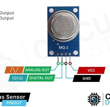
MQ-2 Gas Sensor Pinout
The MQ-2 gas detection sensor module features four pins: VCC, GND, Aout, and Dout. These pins allow you to retrieve the necessary data from the sensor. Below is the pinout for the MQ-2 gas detection sensor:
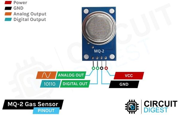
VCC is the power supply pin for the gas detection sensor, which should be connected to the 5V supply.
GND is the ground pin and must be connected to the ground pin of the Arduino.
DOUT is the digital output pin, where a low output indicates no gas or smoke is detected, while a high output signals the presence of gas or smoke.
AOUT is the analog output pin, providing a signal that varies between VCC and ground based on the detected gas level.
MQ-2 Gas and Smoke Sensor Module – Components
The MQ-2 sensor is commonly used in Arduino projects to detect hazardous or flammable gases and smoke, making it a popular choice among beginners. These sensors are affordable, easy to use, and feature a wide sensing range that can be adjusted to fine-tune sensitivity. Below are the part markings for the MQ-2 gas sensor:
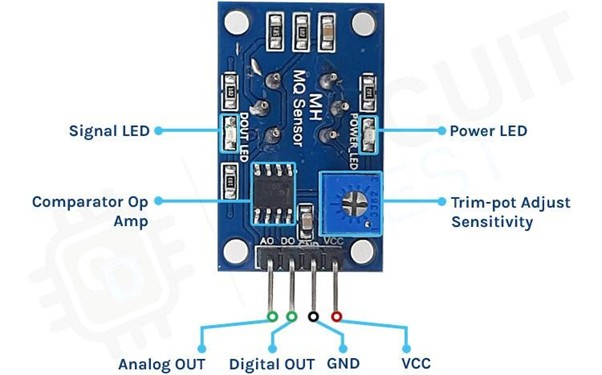
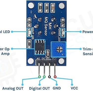
Like other basic sensor modules, the MQ-2 gas and smoke sensor module has four pins: two for VCC and GND, and the other two provide both analog and digital output data. To power the circuit, we connect it to the 5V pin of the Arduino, as the operating voltage range for this module is 5V with a tolerance of ±0.1%.
As shown in the image above, the module includes two onboard LEDs. The power LED lights up when the board is powered, while the Dout LED illuminates when the threshold value, set by the potentiometer, is reached. The board also features an onboard comparator OP-Amp, which is responsible for converting the analog signal from the gas sensor into a digital signal. Additionally, there’s a sensitivity adjustment trim-pot that allows us to fine-tune the sensor’s sensitivity. Finally, the board includes resistors and capacitors for decoupling and filtering.
How the MQ-2 Gas Sensor Module Works
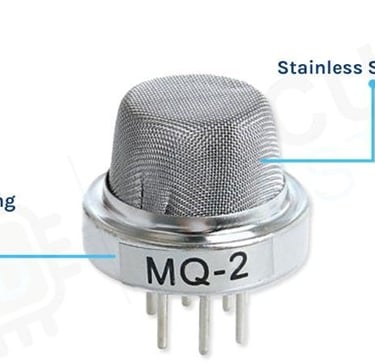
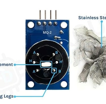
The MQ-2 gas sensor requires a heating element to properly detect combustible gases. However, placing a heating element directly in contact with combustible gases could be dangerous. To prevent this, the sensor is designed with an anti-explosion safety network made of two thin layers of stainless steel mesh, as shown in the image below. The heating element is housed inside this mesh structure.
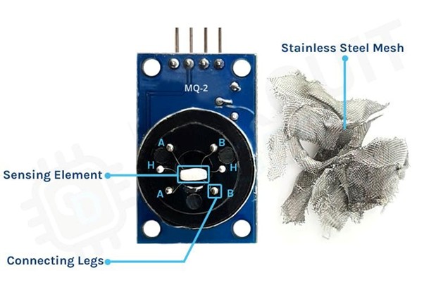
This mesh also offers protection against dust and other suspended particles, allowing only gaseous elements to enter and interact with the sensor. If we were to remove the outer mesh, we’d reveal the two main components of the sensor. The first is the heating element, made of nichrome wire, and the second is the sensing element, made of a platinum wire coated with tin dioxide.
For safety reasons, we’ve done the disassembly for you. The image below shows the sensor with the mesh removed. You can clearly see the sensor's sensing element, which was previously covered by the stainless steel mesh. The star-shaped pins you see are part of the structure formed by the sensing and heating elements, connected to the six legs of the sensor. Additionally, the black base of the sensor is made of Bakelite, which helps improve thermal conductivity.

Pre-Heat Time for MQ-2 Gas Sensor
When working with the MQ-2 gas sensor, there is a pre-heat or stabilization period required for the sensor to function properly. According to the device’s datasheet, it recommends a pre-heat time of 24 hours. But does this mean you need to keep the sensor powered on for a full 24 hours before using it?
The simple answer is no. The 24-hour pre-heat time is necessary to achieve the typical performance data shown in the datasheet, as the data is measured after 24 hours of continuous operation in the lab. For general use, the sensor can reach thermal equilibrium in about 30 minutes, and you’ll likely be within a few percent of the datasheet data after just a few minutes of operation.
The 24-hour preheat time is crucial only if you need highly accurate gas concentration measurements. In that case, you must ensure the sensor is well-calibrated and consider compensating for other environmental factors like temperature and humidity.
The MQ-2 gas sensor can be used for detecting gases and measuring the concentration of butane and hydrogen in PPM (parts per million). It's important to note that detecting gas presence and measuring its concentration are two distinct processes. This article primarily focuses on detecting the gas level and its concentration increase. If you aim to accurately calculate the gas concentration in PPM, the procedure differs, but we will briefly touch on it as well.
How to measure LPG, Butane or Hydrogen Gas concentration in PPM using MQ-2 sensor?
This is a very precise sensor that is calibrated to measure the PPM of a particular gas present in the atmosphere.
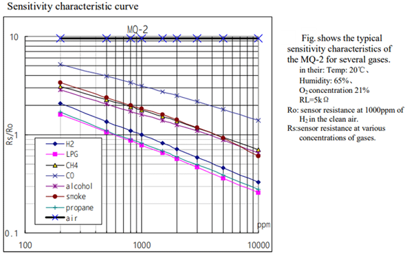
In the logarithmic graph, RS represents the sensing resistance when a specific gas is present, while R0 denotes the sensing resistance in clean air. This sensor is designed to detect gases such as H2, LPG, CH4, and CO, meaning that the sensor's resistance will vary based on the concentration of H2 or LPG in the atmosphere.
Let's take an example of the LPG curve which is the pink one and see how we can calculate the slope of the curve, for that lets start with the X and Y coordinates that is 200 and 1.8 approximately So, the first data point from the logarithmic scale is (log200, log2) which is (2.3,0.0.255). The point for the ending curve is X1 and Y1 that is 1000 and 0.18 that becomes (log1000, log0.18) thus it becomes (4, -0.744). To get the slope of the curve, the formula is
=(Y1- Y) / (X1-X)
= (-0.744 - 0.255) / (4 - 2.3) =-0.587
That's how you can calculate the slope for this sensor.
Internal Schematic for MQ-2 Gas Sensor Module
The circuit diagram for the MQ-2 Gas and Smoke Detection Sensor Module is presented below. The schematic for this module is straightforward and requires only a few components to assemble. If you're looking to quickly build this circuit, the diagram provided below will be helpful.
MQ-2 Combustible Gas Sensor with Arduino UNO – Wiring Diagram
Now that we have a clear understanding of how the MQ-2 gas sensor operates, we can proceed with connecting the necessary wires to the Arduino UNO. This section will be divided into two parts: one for the analog output and another for the digital output. Let's start with the analog circuitry.
To power the sensor, we'll use the 5V and GND pins on the Arduino UNO board. The output pin from the sensor will be connected to the A0 pin on the Arduino.
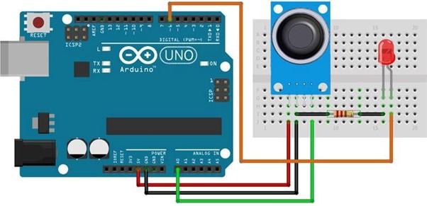
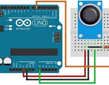
As shown in the above schematic we have connected an LED to digital PIN 6 of the Arduino and the analog pin is connected to the A0 pin of the arduino, and the ground pin is common in between the led and the sensor. We will program the Arduino so that the brightness of the LED will change depending on the concentration of the gas present in the atmosphere.
The code for interfacing the MQ-2 gas sensor module with Arduino is simple and easy to follow. It reads the analog data from the sensor and adjusts the brightness of an LED based on the received data. Keep in mind that we are processing only the analog data from the sensor; for the digital data, you can observe the onboard LED on the module lighting up.
Arduino Code for Interfacing MQ-2 Gas Sensor Module
#define ledPin 6 // led pin is connected to GPIO 6 #define sensorPin A0// sensor output is connected to A0
void setup() { Serial.begin(9600);
pinMode(ledPin, OUTPUT); //ledpin is set to output mode
digitalWrite(ledPin, LOW);//ledpin is turned off initially }
void loop() {
Serial.print("Analog output: ");// Serial.println(readSensor());
delay(500); }
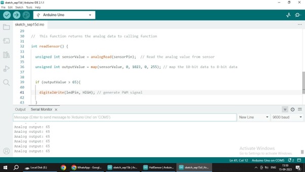
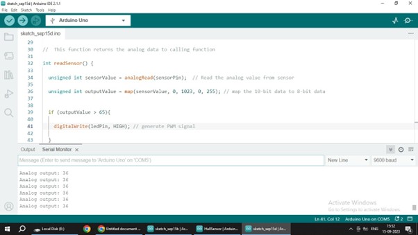
int readSensor() // This function returns the analog data to calling function {
unsigned int sensorValue = analogRead(sensorPin); // Read the analog value from sensor
unsigned int outputValue = map(sensorValue, 0, 1023, 0, 255); // map the 10-bit data to 8-bit data
if (outputValue > 65) {
digitalWrite(ledPin, HIGH); // led is turned on
}
else {
digitalWrite(ledPin, LOW); // led is turned off
return outputValue; // Return analog moisture value }
}
Working