
Pulse sensor with arduino
You can connect a MAX30102 Pulse Oximeter and Heart Rate Sensor to an Arduino, but one of the main challenges with this sensor is its inconsistency and limited support for the Arduino IDE. Therefore, in this article, we decided to use a simpler pulse sensor to measure heartbeats. This pulse sensor is a well-designed, plug-and-play heart rate sensor for Arduino, offering ease of use and a wide range of applications. It’s an ideal choice for students, artists, athletes, manufacturers, and game or mobile developers who wish to incorporate real-time heart rate data into their projects.
TRAINING
2/1/20254 min read
Introduction:
You can connect a MAX30102 Pulse Oximeter and Heart Rate Sensor to an Arduino, but one of the main challenges with this sensor is its inconsistency and limited support for the Arduino IDE. Therefore, in this article, we decided to use a simpler pulse sensor to measure heartbeats. This pulse sensor is a well-designed, plug-and-play heart rate sensor for Arduino, offering ease of use and a wide range of applications. It’s an ideal choice for students, artists, athletes, manufacturers, and game or mobile developers who wish to incorporate real-time heart rate data into their projects.
Pulse Sensor Pinout:
The pulse sensor comes with a flat ribbon cable featuring three male header connectors. The pinout of the pulse sensor is outlined below.
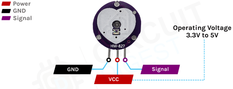
S (Signal): This is the analog output pin of the sensor module that provides an analog reading directly from the sensor.
VCC: The power supply pin of the sensor. Connect it to the 5V pin of the Arduino.
GND: The ground pin of the sensor. Connect it to the ground pin of the Arduino.
How Does a Pulse Sensor Module Work?
The basic operation of the optical pulse sensor is simple and easy to understand. The sensor emits green light with a 550 nm wavelength through the skin and measures the reflected light. This method of pulse detection is known as Photoplethysmogram (PPG). The working principle of the pulse sensor is as follows.
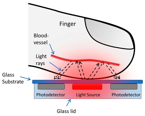
The pulse sensor emits light through the skin and measures the reflected light with a photodetector. This method of pulse detection using light is known as Photoplethysmogram (PPG). The sensor's functionality can be broken down into two main components: heart rate measurement and blood oxygen level measurement.
Oxygenated hemoglobin has a unique property of absorbing a specific amount of green light. As the oxygen content in the blood increases, the blood becomes redder, which increases light absorption and reduces reflection. As blood flows through the veins in the finger, the reflected light fluctuates, creating an oscillating waveform. By analyzing this waveform, we can calculate the heart rate. The signal from the sensor is small and noisy, so it is filtered using a low-pass filter and then amplified by an op-amp before being read by the Arduino.
Pulse Sensor Module – Components
This is a low-power, cost-effective, and durable sensor, making it a popular choice for various applications that require heart rate measurement.
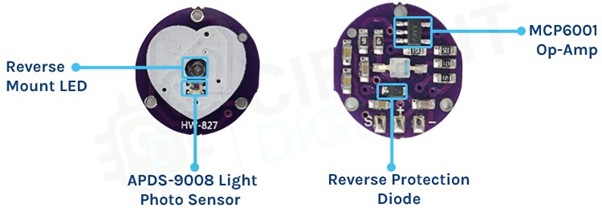
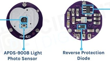
When looking at the front of the sensor, you'll see only the LED and photodiode. However, the actual circuit is located on the backside of the sensor. The low-power, high-bandwidth op-amp in the circuit is designed to provide gain, while a reverse voltage protection diode safeguards the circuit from electrostatic discharge (ESD) and reverse voltage. Additional capacitors and resistors on the PCB are used for an RC filter, which helps reduce any external noise in the circuit.
Circuit Diagram for Pulse Sensor Module
The circuit diagram of the pulse sensor module is shown below. The key components of this circuit include a 10uF filter capacitor, followed by a green LED and a 470Ω resistor.
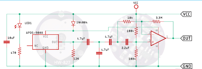
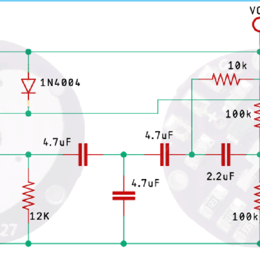
The 470Ω resistor in the circuit serves as the current-limiting resistor for the sensor module. Additionally, the circuit is powered through a diode that serves two purposes: it provides reverse polarity protection and safeguards the circuit from transients. After passing through the diode, the power is distributed to the MCP6001 op-amp and the APDS-9008 photodiode sensor IC. Since the output amplitude from the sensor IC is low and noisy, it needs to be filtered using an RC low-pass filter. The filtered signal is then amplified by the op-amp, allowing the microcontroller to process the data.
Arduino Pulse Sensor – Connection Diagram
Now that we have a complete understanding of how the pulse sensor operates, let's connect all the necessary wires to the Arduino UNO board. In this section, we will walk through the connection process.
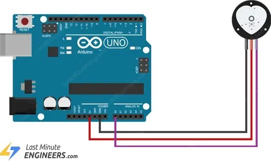
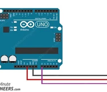
The Arduino pulse sensor circuit diagram is shown in the figure above. We use the A0 pin of the Arduino to read the data from the sensor, while the sensor's power pins are connected to the 5V and Ground pins of the Arduino. The practical test hardware setup is shown below.
Arduino Code for Interfacing Pulse Sensor Module with Arduino
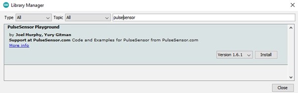
The Arduino code for interfacing with the pulse sensor is simple and easy to understand. Most of the complex tasks are handled by the PulseSensorPlayground.h library. However, note that this is not a built-in library and must be installed separately using the library manager. To do this, search for "pulsesensor" in the library manager window and install the PulseSensor Playground library by Joel Murphy and Yury Gitman. Once the library is installed and everything is set up, we can proceed with writing the code.
As mentioned earlier, the code for this project is quite simple, which is why we’ve used an example from the library to handle most of the complex tasks for us. However, let’s not skip over it and take a closer look at how the code functions.