
Sound sensor with an arduino
A sound sensor is a low-cost, easy-to-use device designed to detect sound waves traveling through the air. In addition to detecting sound, it can also measure its intensity and convert it into an electrical signal, which can be read by a microcontroller. But how exactly does a sound sensor work? What are its applications? And how can it be interfaced with an Arduino? If you're looking for answers to these questions, this document will guide you through them.
TRAINING
2/3/20255 min read
Introduction
A sound sensor is a low-cost, easy-to-use device designed to detect sound waves traveling through the air. In addition to detecting sound, it can also measure its intensity and convert it into an electrical signal, which can be read by a microcontroller. But how exactly does a sound sensor work? What are its applications? And how can it be interfaced with an Arduino? If you're looking for answers to these questions, this document will guide you through them.
Sound Sensor Pinout
The sound sensor module comes with four pins: VCC, GND, Digital Out (DO), and Analog Out (AO). You can either use:
The AO pin for analog readings.
The DO pin for digital output.
Below is a breakdown of the sound sensor pin configuration:
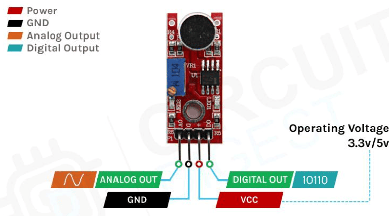
Sound Sensor Pin Description
VCC: The power supply pin of the sound sensor, which can be connected to 3.3V or 5V. However, keep in mind that the analog output varies based on the supplied voltage.
GND: The ground pin of the sound sensor module, which must be connected to the ground (GND) of the Arduino.
DOUT (Digital Output): This pin provides a digital output—LOW when no sound is detected and HIGH when the sensor detects sound.
AOUT (Analog Output): This pin provides an analog signal directly from the sound sensor, representing the intensity of the detected sound.
How Does a Sound Sensor Module Work?
The operation of the sound sensor module is straightforward. The key component of the module is a condenser microphone, which captures sound waves. When sound waves hit the microphone's diaphragm, it generates an analog signal. This signal is then processed by an operational amplifier (op-amp), which converts it into a digital output, making it easy for the microcontroller to interpret.
The core component of a sound sensor is a microphone. Various types of microphones exist, including Carbon Microphones, Fiber Optic Microphones, Ribbon Microphones, and Laser Microphones. However, the sound sensor module used in this project features a condenser microphone. Below is an image of the sound sensor module.
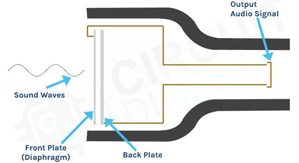
As seen in the image, a condenser microphone consists of two charged metal plates: the diaphragm and the backplate. Together, these plates form a capacitor. When a sound wave strikes the diaphragm, it begins to vibrate, altering the distance between the two plates. This movement changes the capacitance, generating an electrical signal that corresponds to the detected sound. The onboard op-amp then processes this signal.
The module also features two onboard LEDs:
One LED indicates power when the module is active.
The second LED lights up when the detected audio signal surpasses the threshold set by the potentiometer.
Sound Sensor Module – Features & Applications
This sensor is widely used for projects such as sound-reactive switches or LED visualizers, making it popular among beginners. It is low-cost, low-power, durable, and has an adjustable sensing range, making it suitable for various sound detection applications.
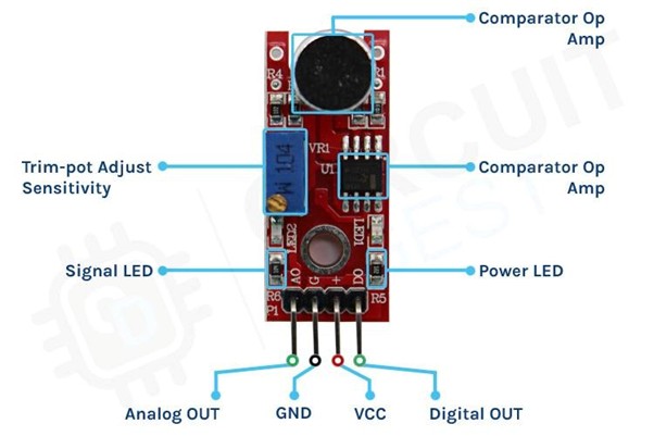
This sensor features three pins: two power pins, VCC and GND, and two signal pins—analog and digital, as shown in the diagram above. It is equipped with an onboard power LED and a signal LED. The power LED lights up when the board is powered, while the signal LED turns on when the circuit is triggered. The board also includes a comparator op-amp, which converts the incoming analog signal into a digital signal. Additionally, there is a sensitivity adjustment potentiometer that allows you to fine-tune the device's sensitivity. Lastly, the condenser microphone is used to detect sound. Together, these components form the complete Sound Sensor Module.
Circuit Diagram for Sound Sensor Module
The schematic diagram for the Sound Sensor module is shown below. The design is straightforward and requires only a few common components to build. If you don't have a pre-built module available, you can refer to the schematic to test your project.
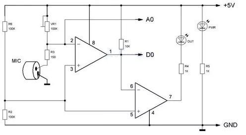
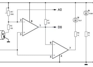
In the schematic, we have an LM393 op-amp, which is a low-power, low-cost, and low-offset voltage operational amplifier that can be powered by either a 3.3V or 5V supply. It's important to note that the analog output voltage of the device will vary depending on the supply voltage. The primary function of this op-amp is to convert the incoming analog signal from the sensor probe into a digital signal. Additionally, there is a 10K potentiometer used to set the reference voltage for the op-amp, which also determines the reference voltage for the analog output of the module.
When the input voltage from the sensor falls below the threshold voltage set by the potentiometer, the output of the op-amp will go low. The module also includes two LEDs: a power LED and a trigger LED. The power LED lights up when the board is powered, while the trigger LED turns on when the sensor detects sound that surpasses the threshold. This is the basic operation of the circuit.
Sound Sensor with Arduino UNO – Connection Diagram
Now that we have a clear understanding of how the Sound Sensor works, let's connect all the necessary wires to the Arduino, as shown in the diagram below.
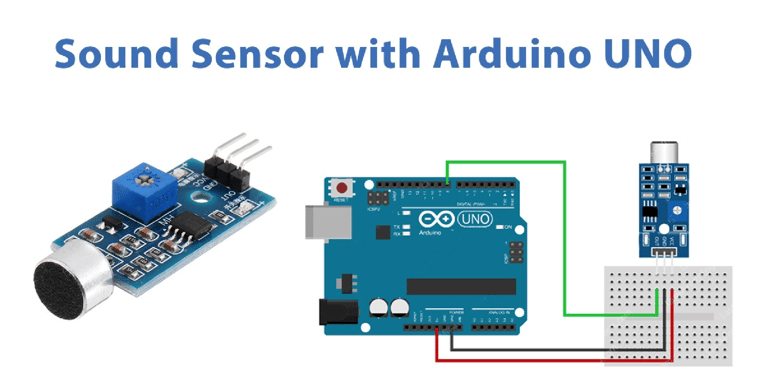
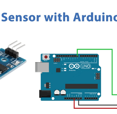
Connecting the Sound Sensor to the microcontroller is straightforward. As the sensor outputs an analog signal, it's easy to process this signal using the Arduino's ADC. We can then light up LEDs to indicate the intensity of the sound detected by the microcontroller. The circuit connection is simple: we connect the VCC and ground from the Arduino to the sensor module, and use GPIO12 to connect an LED. The ground of the Arduino is also connected to the ground of both the LED and the sensor.
Arduino Sound Sensor Code
The Arduino Sound Sensor code is simple and easy to follow. We read the analog data from the sensor and light up LEDs to visualize the intensity of the sound detected by the sensor. Additionally, you can observe that the onboard LED on the module lights up when a loud sound is detected by the sensor.
int ledPin=12; // initialising the pin 12 as the led pin int sensorPin=8; // initialising pin 8 as the sensor output pin boolean val =1; void setup() { pinMode(ledPin, OUTPUT); // set arduino pin to output mode pinMode(sensorPin, INPUT); // set arduino pin to input mode } void loop ()
{ val =digitalRead(sensorPin);//read the sensor pin with the digitalRead() function and store the value to the val variable.
if (val==LOW) // when the sensor detects a signal above the threshold value, LED flashes { digitalWrite(ledPin, HIGH); //LED turns ON delay(1000); } else { digitalWrite(ledPin, LOW);//LED turns OFF }
}
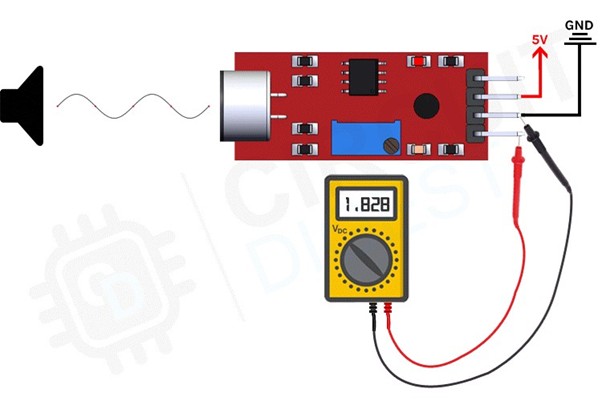
Working:
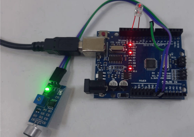
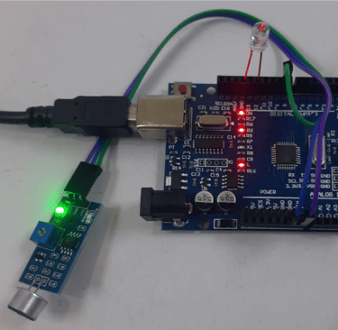
Fig: LED is OFF when there is no sound
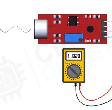
Fig: LED is ON when there is no sound