
Vibration sensor module is interfaced with Arduino UNO
Machines and equipment, especially costly ones, can be severely damaged by vibrations. To detect if a machine or equipment is experiencing vibrations, a vibration sensor becomes essential. Identifying objects that continuously vibrate is relatively simple when using the right sensor. There are various types of vibration sensors in the market that detect vibrations by measuring acceleration or velocity and can deliver accurate results. However, these sensors, especially accelerometers, tend to be expensive. Accelerometers are highly sensitive and are even used in earthquake detection circuits.
SIMPLE ARDUINO CODES
2/3/20253 min read
Introduction:
Machines and equipment, especially costly ones, can be severely damaged by vibrations. To detect if a machine or equipment is experiencing vibrations, a vibration sensor becomes essential. Identifying objects that continuously vibrate is relatively simple when using the right sensor. There are various types of vibration sensors in the market that detect vibrations by measuring acceleration or velocity and can deliver accurate results. However, these sensors, especially accelerometers, tend to be expensive. Accelerometers are highly sensitive and are even used in earthquake detection circuits. On the other hand, more affordable and specialized vibration sensors, such as the SW-420, can effectively detect vibrations, and we’ll be interfacing this sensor with an Arduino Uno.
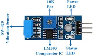

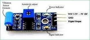
The SW-420 vibration module operates within a voltage range of 3.3V to 5V. It utilizes an LM393 comparator to detect vibrations that exceed a set threshold and provides digital output data in the form of Logic Low (0) or Logic High (1). Under normal conditions, the sensor outputs Logic Low, but when a vibration is detected, it switches to Logic High. The module includes two LEDs: one indicates the power state, and the other shows the sensor's output. Additionally, the module features a potentiometer, which allows for adjusting the vibration threshold. For this project, we will power the module using a 5V supply.
Pinout diagram of the SW-420 Vibration Sensor Module:

Components Required
● Arduino UNO
● SW-420 Vibration Sensor Module
● 5mm LED (Any Colour)
● Jumper Wires(Hookup Wires)
● USB Cable for Uploading Program
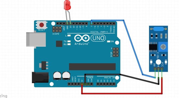
Arduino Vibration Sensor Circuit Diagram
The schematic for interfacing Vibration sensor with Arduino uno is given below.
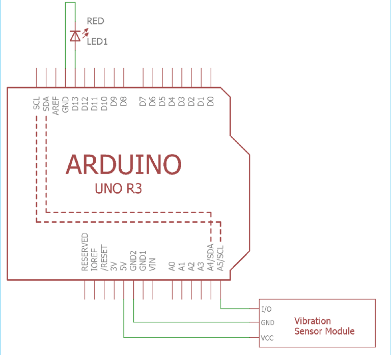
The LED is connected to the D13 pin on the Arduino. The module is powered using the 5V pin on the Arduino. The ground and 5V pins power the Arduino, while the A5 pin is used to receive data from the vibration sensor.
The circuit is built by connecting the SW-420 vibration sensor module and the LED to the Arduino Uno as shown in the setup.
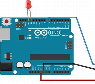
The circuit does not require an additional breadboard and can be directly tested with the Arduino UNO board. The LED connected to Pin 13 of the Arduino will blink when the vibration sensor is triggered by any vibrations. If the sensor doesn't respond, double-check the connections and ensure the power is properly supplied. Avoid any loose connections between the sensor and the microcontroller.
Code:
int led_pin = 13 ;// initialising the pin 9 as the led pin int vib_sensor_pin = 7 ;// initialising pin 12 as the sensor output pin
int vib_pin = LOW ; // state of sensor void setup ( ) { pinMode ( led_pin , OUTPUT ); // declaring led pin as output pin pinMode ( vib_sensor_pin , INPUT ); // declaring sensor pin as input pin for Arduino Serial.begin ( 9600 );// setting baud rate at 9600
} void loop ( ) { vib_pin = digitalRead (vib_sensor_pin) ; // reading from the sensor if (vib_pin == HIGH ) // applying condition { digitalWrite ( led_pin , HIGH ) ;// if state is high, then turn high the led delay(1000); } else { digitalWrite ( led_pin , LOW ) ; // otherwise turn it low } delay(1000);
}
Working
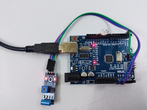
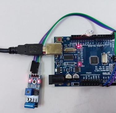
Fig: LED is OFF when there is no vibration
Fig: LED turns ON when we vibrate the sensor